
Installation Instructions User Manual

Allen-Bradley Redundant Power Supplies10
Publication 1771-IN030B-EN-P - July 2002
Alarm Relay and AC Power Connections
Connect Input Power
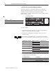
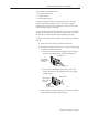
The following figure shows the overall configuration of the ac power
connections.
The two undesignated terminals do not connect to any electrical
circuit on the module. Each of the three functional terminals accepts
a single 14-AWG wire max.
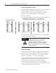
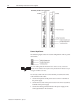
To correctly connect the wire to the terminal you connect the wires
to the terminal in this order:
• connect the high side of the power source to the L1 terminal of
the power supply
• connect the low side of the power source to the L2 or N (neutral)
terminal of the power supply
• connect the GND (ground) terminal of the power supply to the
central ground bus in the enclosure
"