
Installation Instructions Owner's manual

Power Supply Modules 11
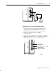
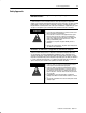
$# % !
120V
AC
$#!
Equipment
Ground
Grounding
Electrode
Conductor
! $ $"
%
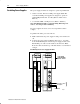
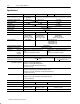
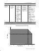
Connecting the 1771-P5 and -P5E Power Supplies
1. Remove the protective cover from the terminal block by
squeezing the prongs and lifting the protective cover.
2. Connect the positive dc line to the top terminal (DC).
3. Connect the negative dc line to the middle
terminal (COM).
4. Connect the bottom terminal (labeled GND) to the ground bus.
5. Tighten terminal block screws to 7 pound–inches (0.5Nm).
6. Replace the protective cover on the terminal block.
24V
DC
Connect central
ground bus to GND
dc Negative connects to COM
dc Positive
connects to DC
%