
Installation Instructions

Selectable Contact Output Module6
Publication 1771-IN037B-EN-P - July 2002
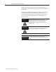
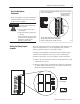
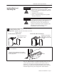
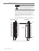
3. Reinstall the circuit board in the module and replace the cover.
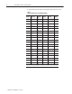
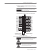
Table A
Jumper Identification for Individual Outputs
Terminal
Number
Function
Jumper
Number
Terminal
Number
Function
Jumper
Number
1 Common 0 21 Common 2
2 Output 00 LĆ00 22 Output 00 HĆ00
3 Output 01 LĆ01 23 Output 01 HĆ01
4 Output 02 LĆ02 24 Output 02 HĆ02
5 Output 03 LĆ03 25 Output 03 HĆ03
6 Output 04 LĆ04 26 Output 04 HĆ04
7 Output 05 LĆ05 27 Output 05 HĆ05
8 Output 06 LĆ06 28 Output 06 HĆ06
9 Output 07 LĆ07 29 Output 07 HĆ07
10 Not used 30 Not used
11 Common 1 31 Common 3
12 Output 10 LĆ10 32 Output 10 HĆ10
13 Output 11 LĆ11 33 Output 11 HĆ11
14 Output 12 LĆ12 34 Output 12 HĆ12
15 Output 13 LĆ13 35 Output 13 HĆ13
16 Output 14 LĆ14 36 Output 14 HĆ14
17 Output 15 LĆ15 37 Output 15 HĆ15
18 Output 16 LĆ16 38 Output 16 HĆ16
19 Output 17 LĆ17 39 Output 17 HĆ17
20 Not used 40 Not used
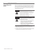
If using multiple power supplies, do not exceed the specified isolation voltage.