
User Manual

AC (24V) Output Module 7
Publication
17715.41 - May 1996
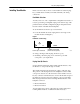
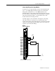
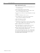
The front panel of your module contains one green, module active
indicator, and 16 red status indicators (Figure 4). The 1771-OND
performs diagnostics in a handshaking mode when first powered up.
Upon successful completion of the diagnostics, the green module
active indicator lights. It turns off if a fault occurs in the data paths
or the opto-isolators.
The red status indicators are provided for system logic side
indication of individual inputs. When a red indicator lights, voltage
is present on the terminal. The module transfers this information to
the backplane for the processor to read.
Figure 4
Status
Indicators
ACTIVE
00
01
02
03
04
05
06
07
10
11
12
13
14
15
16
17
Module Active Indicator (green)
00 to 17 Status Indicators (red)
10676I
Interpreting the Status
Indicators