Important User Information Because of the variety of uses for the products described in this publication, those responsible for the application and use of this control equipment must satisfy themselves that all necessary steps have been taken to assure that each application and use meets all performance and safety requirements, including any applicable laws, regulations, codes and standards. The illustrations, charts, sample programs and layout examples shown in this guide are intended solely for example.
Summary of Changes This release of the publication contains updated information from the last release. Updated Information This publication covers the Series B version of the Analog Output module.In addition, this version of the manual contains information formally included in publication 1771-6.5.30–RN1, dated December 1995. A revised circuit board layout has the configuration jumpers relocated from previous versions.
SOC-2 Summary of Changes
Manual's Purpose This manual shows you how to use the analog output module with an Allen-Bradley programmable controller. It describes methods for installing, programming, calibrating, and troubleshooting your module. Audience To make efficient use of your module, you must be able to program and operate an Allen-Bradley programmable controller. In particular, you must be able to program block transfer instructions. In this manual we assume that you know how to do this.
P–2 Preface Appendices Related Products Title A Specifications B Block Transfer with MiniĆPLCĆ2 and PLCĆ2/20 Processors C Data Table Formats You can install your output module in any system that uses Allen-Bradley programmable controllers that have block transfer capabilities and the 1771 I/O structure. For more information on your programmable controllers, contact your nearest Allen-Bradley office. Product Compatibility The 1771-OFE module can be used with any 1771 I/O chassis.
Overview of the Analog Output Module Chapter 1 Module Installation Chapter 2 Chapter Objectives . . . . . . . . . . . . . . . . . . . . . . . . . . . . . . . . . . . Module Description . . . . . . . . . . . . . . . . . . . . . . . . . . . . . . . . . . . Module Features . . . . . . . . . . . . . . . . . . . . . . . . . . . . . . . . . . . Output Ranges . . . . . . . . . . . . . . . . . . . . . . . . . . . . . . . . . . . .
ii Table of Contents Module Programming Chapter 4 Chapter Objectives . . . . . . . . . . . . . . . . . . . . . . . . . . . . . . . . . . . Block Transfer with the Analog Output Module . . . . . . . . . . . . . . . . Block Transfer Programming Formats . . . . . . . . . . . . . . . . . . . . . . Block Transfer Programming Ć PLCĆ2 Family Processors Only . . . . . Block Transfer Programming Ć PLCĆ3 Family Processors Only . . . . . Block Transfer Programming Ć PLCĆ5 Family Processors Only . . . . .
iii Table of Contents Specifications Appendix A Specifications . . . . . . . . . . . . . . . . . . . . . . . . . . . . . . . . . . . . . . . Block Transfer with MiniĆPLCĆ2 and PLCĆ2/20 Processors Appendix B Data Table Formats Appendix C Multiple GET Instructions . . . . . . . . . . . . . . . . . . . . . . . . . . . . . . . Rung 1 . . . . . . . . . . . . . . . . . . . . . . . . . . . . . . . . . . . . . . . . . . Rungs 2 and 3 . . . . . . . . . . . . . . . . . . . . . . . . . . . . . . . . . . . . .
Table of Contents
Overview of the Analog Output Module What This Chapter Contains About the Analog Output Module Read this chapter to familiarize yourself with the analog output module.
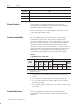
1-2 Module Features In the programmable controller system, the analog output module provides the following functions: • • • • • four individually isolated differential outputs selectable scaling to engineering units selectable data format selectable voltage ranges (1771-OFE1 only) no external power required--power is drawn from the 1771 I/O chassis backplane.
1-3 How Analog Modules Communicate with Programmable Controllers The processor transfers data to the module (block transfer write) and from the module (block transfer read) using BTW and BTR instructions in your ladder diagram program. These instructions let the processor send output values to the module, establish the module’s mode of operation (see illustration below) and receive status information from the module.
What This Chapter Contains In this chapter, you will read about: For information on See page ,*-)& + " 1, 2/,-" + +&,+ '" 1&3"0 ) 2) 1" 1%" ,4"/ ".
2-2 For specific information required by EN 61131-2, see the appropriate sections in this publication, as well as the following Allen-Bradley publications: • Industrial Automation Wiring and Grounding Guidelines For Noise Immunity, publication 1770-4.1 • Guidelines for Handling Lithium Batteries, publication AG-5.4 • Automation Systems Catalog, publication B111 This equipment is classified as open equipment and must be mounted in an enclosure during operation to provide safety protection.
2-3 Determine Module Location in the I/O Chassis You can place your module in any I/O module slot of the I/O chassis with the following guidelines: • Do not put the module in the same module group as a discrete high-density module. • Avoid placing output modules close to ac modules or high-voltage dc modules. • Group output modules together within an I/O chassis whenever possible to minimize noise interference from other modules. • You can put two output modules in the same module group.
2-4 This is a significant safety feature. You can choose to have the module’s outputs go to the maximum, minimum, or middle of their respective ranges or hold their last state if a module or system fault occurs or if the system processor changes from RUN to PROG mode. You do this by placing the LAST STATE configuration jumpers on eight (four jumpers on sets of pins) of the stake pins marked MAX, MIN, MID on the module’s circuit board (Figure 2.1).
2-5 Figure 2.1 LAST STATE Configuration Jumper Last State Output Level Configuration Jumpers Front of Circuit Board HOLD LAST STATE MIN MID MAX Table 2.A lists the output ranges and their minimum, maximum, and middle values. Table 2.
2-6 Rack switch 1 determines what output conditions occur during a rack fault. Configuration Jumper Setting Rack Switch 1 S tti Setting %& & & % & MIN MID MAX HOLD LAST STATE %& & & %& & & %& & & %& & & ! ) %& & & To set the last state configuration jumpers, proceed as follows. ! ATTENTION: Do not insert modules into or remove modules from the I/O chassis while system power is ON.
2-7 Figure 2.
2-8 Install the Module and Field Wiring Arm ! ATTENTION: Remove power from the 1771 I/O chassis backplane and field wiring arm before removing or installing an I/O module. • Failure to remove power from the backplane or wiring arm could cause module damage, degradation of performance, or injury. • Failure to remove power from the backplane could cause injury or equipment damage due to possible unexpected operation.
2-9 Connect the Wiring The analog devices connect to the analog module through a field wiring arm (cat. no. 1771-WC). The field wiring arm pivots on the front of the I/O chassis to connect with the module. You can remove the module from the chassis without disconnecting user wiring because wiring connections are made on the field wiring arm. The connection diagram (Figure 2.5) shows connections to the field wiring arm.
2-10 The module requires shielded cable for signal transmission to the analog devices. Use Belden 8761 shielded cable, which consists of a single insulated, twisted-pair of conductors, covered along their entire length by a foil shield and encased in plastic. The shield reduces the effect of induced noise at any point along the cable. Ground the Chassis and Module You must ground the shield at the chassis end only. We recommend connecting each output cable’s shield to a properly grounded common bus.
2-11 Interpreting the Indicator Lights The front panel of the module contains a green RUN and a red FLT (fault) indicator. At power-up, the red FLT indicator lights and remains ON during an initial module self-check. If a fault is found initially or occurs later, the red FLT indicator stays lit. If a fault is not found, the red indicator will turn off and the green RUN indicator will turn on and remain on.
Configuring Your Output Module What This Chapter Contains In this chapter, you will read about: Configuring Your Module For information on See page Configuring Your Module . . . . . . . . . . . . . . . . . . . . . . . . . . . Configuration Word . . . . . . . . . . . . . . . . . . . . . . . . . . . . . . . Default Configuration . . . . . . . . . . . . . . . . . . . . . . . . . . . . . . Data Format . . . . . . . . . . . . . . . . . . . . . . . . . . . . . . . . . . . . Scaling . . . . . . .
3-2 Note: Programmable controllers that use 6200 software programming tools can take advantage of the IOCONFIG utility to configure this module. IOCONFIG uses menu-based screens for configuration without having to set individual bits in particular locations. Refer to your 6200 software literature for details. Programmable controllers that use process configuration and operation software (cat. no.
3-3 Configuration Word Word 5 of the block transfer write is the module configuration word (Figure 3.1). It contains information on: • data polarity • scaling polarity • data format Figure 3.1 Configuration Block Transfer Write Word 5 Word/Dec.
3-4 Word Word 5 continued Decimal Bit (Octal Bit) Description 09 (11) When set (1), indicates negative maximum scaling value for Channel 3. When reset (0), indicates positive maximum scaling value for channel 3. 10 (12) When set (1), indicates negative minimum scaling value for Channel 4. When reset (0), indicates positive minimum scaling value for channel 4. 11 (13) When set (1), indicates negative maximum scaling value for Channel 4.
3-5 Some examples of how to determine the value of the data word needed to produce the desired output voltage or current follow: Example 1 Output Range Data Format Desired Output D I/Bit 4Ć20mA BCD (0Ć4095) 9.5mA 0.0039mA/Bit (from Table 3.B) Remember, 4mA corresponds to scale minimum (9.5mA Ć 4mA) 0.0039mA/Bit @ 1410 (decimal) = 0001 0100 0001 0000 (BCD) You would enter 1410 (BCD) or 0001 0100 0001 0000 into the data word in order to get an output of 9.5 mA.
3-6 Scaling Scaling is the conversion of unscaled data to engineering units--such as gallons/minute, degrees centigrade, and pounds/square inch. You can use the scaling feature to send the data for each channel to the module in an optional scaled value representing actual engineering units. This value is scaled by the module to a proportional binary value before it is used by the corresponding channel. The resolution of this data is one part in 4095.
3-7 The largest value that you can enter for a maximum scaling value is 9999. The smallest value you can enter for a minimum scaling value is -9999 (the minus sign is implemented by setting the appropriate bit in the configuration word). Important: The maximum scale value must be larger than the minimum scale value. If not, block transfers continue but data is not acknowledged by the module’s microprocessor. Outputs remain in their last state before the fault.
3-8 If you do not wish to scale a particular channel, set the scaling values as shown below. If your range is: Set Maximum Scaling Value to: Set Minimum Scaling Value to: 4095 0000 4095 Ć40951 4Ć20mA 1Ć5V 0Ć10V +10 to Ć10V 1 This also requires you to set the appropriate sign bit in the configuration word for the minimum scaling value. For example, suppose you choose the 1 to 5 volt range and BCD data format for your module.
3-9 Procedure for Configuring Your Module Now that we have explained the purpose and function of each word in the block transfer write block, you should be ready to enter configuration data. Consult your programming manuals for the proper techniques required to set up block transfer instructions with your programmable controller. Refer to chapter 4 for example programs. Important: Chapter Summary A block transfer write length of 0 will result in a default length of 13.
What This Chapter Contains Block Transfer with the Analog Output Module In this chapter you will read about: For information on See page %( $ * '+ * /#," ," ' %(! -,)-, ( -% %( $ , '+ * *(!* &&#'! (*& ,+ %( $ , '+ * *(!* &&#'! (*& ,+ &#%1 *( ++(*+ ('%1 %( $ , '+ * *(!* &&#'! (*& ,+ &#%1 *( ++(*+ ('%1
4-2 Block Transfer Programming Ć PLCĆ2 Family Processors Only Output data is transferred from the processor’s data table to the module with a write block transfer. Diagnostic information is transferred from the module to the processor’s data table with a read block transfer. In order for these transfers to take place, you must enter certain parameters into your block transfer instructions. A sample program segment with block transfer read and write is shown in Figure 4.
4-3 PLC-2 Family Example Program Module Location Rack 1, Module Group 0, Slot 1 T/C Addresses 030 for Block Transfer Write 031 for Block Transfer Read BTW File (Configuration file) 0200Ć0214 BTR File (Buffer file) 0300Ć0304 Output Data File 0400Ć0404 Storage Bit 050/00 BTW Done Bit 110/16 BTR Done Bit 110Ć17 Module Configuration 1771ĆOFE1 (Voltage Version) Voltage Range 1 to 5V Data Format BCD Scaling Parameters Channels 1 and 2 = No scaling Channel 3 = Ć20 to 275 Channel 4 = 100 to
4-4 Table 4.
4-5 Table 4.
4-6 Figure 4.3 Binary Configuration Word Represented in BCD Channel 3 Minimum Scaling Factor Polarity Set (1) = Negative Reset (0) = Positive Word/Dec.
4-7 Figure 4.4 PLCĆ3 Sample Program Structure Program Action Upon completion of a successful read block transfer, data from the module is moved from the buffer file (block transfer read file) to a storage data file. This prevents the module from using invalid data should block transfer communications fail. At powerĆup, the program performs a write block transfer that configures the module. When the first write block transfer is complete, the program toggles between read and write block transfers.
4-8 Figure 4.
4-9 Figure 4.6 PLCĆ5 Example Program 1 Program Action (Example 1) Rung 1 1 The BTW is writing in an asĆfastĆasĆpossible" mode. As soon as the instruction executes, it is reenabled for another transfer. Instruction execution could also be scheduled using a timer done bit or some other input condition.
4-10 Other Programming Considerations When writing your program, there are some additional programming techniques that you should consider.
4-11 All Four Channels Scaled To scale all four channels, enter a block length of 00 and enter the appropriate scaling values for the four channels, as shown in the following table.
4-12 Figure 4.8 Data Table Structure and GET/PUT Instruction Example for Block Transfer Boundary Word Timer/Counter Accumulated Values Area 030 031 032 033 034 035 0 0 0 0 0 0 0 0 0 0 0 0 0 0 0 0 036 037 First Block Transfer Data Address Last Block Transfer Data Address Address of Block Transfer Boundary W Beginning Address for Timer/Counter S Block Transfer Boundary Word Instruction 036 G 000 Publication 1771Ć6.5.
4-13 Module Update Time Update time is defined as the amount of time it takes for the output module to receive a block transfer scan and update all output channels. Refer to Figure 4.9. The output module updates the four output channels in: • 8 milliseconds when BCD data format and scaling are used • 1.6 milliseconds when binary data format and no scaling are used Block transfer from the processor is inhibited during this time span. Figure 4.
What This Chapter Contains In this chapter, you will read about: Reading Data from the Module For information on See page Reading Data from the Module . . . . . . . . . 5-1 Block transfer read (BTR) programming moves status and data from the module to the processor’s data table in one I/O scan. The processor user program initiates the request to transfer data from the module to the processor.
5-2 Table 5.A Bit/Word Description for Block Transfer Read Word Decimal Bits (Octal Bits) 1 Bits 00Ć15 (00Ć17) Channel 1 DAC input data. 2 Bits 00Ć15 (00Ć17) Channel 2 DAC input data. 3 Bits 00Ć15 (00Ć17) Channel 3 DAC input data. 4 Bits 00Ć15 (00Ć17) Channel 4 DAC input data. Bits 00Ć03 When set, indicate invalid channel data is sent to the module. These bits are not reset until a correct write block transfer is sent. Bit 00 corresponds to Channel 1, Bit 01 to Channel 2, and so on.
Calibrating Your Output Module Chapter Objectives In this chapter, you will read how to calibrate your output module. Tools and Test Equipment For information on See page Tools and test equipment . . . . . . . . . . . . . . . . . . . . . . . . . . . Calibrating your module . . . . . . . . . . . . . . . . . . . . . . . . . . . . Voltage Output version (1771ĆOFE1) . . . . . . . . . . . . . . . . . . Current Output version (1771ĆOFE2) . . . . . . . . . . . . . . . . . . .
6-2 Voltage Output Version (1771ĆOFE1) Preparation for Calibration 1. Turn off the processor and I/O chassis power. 2. Remove the field wiring arm. 3. Remove the analog output module from the I/O chassis. 4. Remove the module covers. 5. Connect the backplane extender card (cat. no. 1771-EX) to the circuit board. 6. Insert the extender card/circuit board assembly in the I/O chassis. 7. Reinstall the field wiring arm.
6-3 6. Connect the voltmeter leads across the top two screws on the field wiring arm (Channel 1). The top screw is positive, and the second (lower) screw is negative. 7. Turn on the processor, I/O chassis, and the industrial terminal. Figure 6.1 Resistor Placement on Field Wiring Arm # $ #*#&! *% '* !* , * * +#+,'*+ " && $ " && $ " && $ " && $ Figure 6.
6-4 Figure 6.3 Location of Configuration Jumpers and Resistor Pots LAST STATE TP1 TP2 TP3 TP10 TP12 Configuration Jumpers (set for +10V scale) Channel 0 Channel 1 Channel 2 Channel 3 R67 R66 R74 R73 4 5 TP6 TP TP P7 P8 TP9 T T Resistor Potentiometers Adjustment Screws R81 R80 R88 R87 12993 8. Place the processor in the TEST or PROG mode. 9. Output full scale (+10V) either with write block transfer data or by placing the LAST STATE configuration jumpers in the MAX position. MAX 10.
6-5 15.Reconnect the voltmeter to the appropriate screws on the field wiring arm. Repeat Steps 9 through 14 for Channels 2, 3, and 4, until you obtain the desired tolerance. Table 6.B lists the appropriate resistor pots for each channel. Table 6.B Resistor Pots Channel Resistor Pots 1 R66, R67 2 R73, R74 3 R80, R81 4 R87, R88 16.Turn off power to the module. 17.Return the LAST STATE configuration jumpers to the position they were in before you started calibration. 18.
6-6 Channel Calibration 1. Disconnect your analog device wires from the module’s field wiring arm. Important: If you have a spare or unused field wiring arm, you may want to temporarily switch it with the module’s present field wiring arm. You can use this spare arm for test purposes in order to avoid disconnecting your analog device wires. Important: The accuracy of this calibration procedure is dependent upon the precision of your load resistors. We suggest using resistors with a tolerance of 0.01%.
6-7 4. Place the LAST STATE configuration jumpers (Figure 6.5) in the MAX position (if they are not there already). MAX Figure 6.5 LAST STATE Configuration Jumpers in MAX Position LAST STATE " $ " % $ " ' Front of Module # $ % # # " !% " #$ #$ $ ( ) 5. Connect the voltmeter leads across the top two screws on the field wiring arm (Channel 1). The top screw is positive, and the second (lower) screw is negative. 6.
6-8 Figure 6.6 Location of Resistor Pots LAST STATE TP1 TP2 TP3 TP10 TP12 Configuration Jumpers (set for +10V scale) Channel 0 Channel 1 Channel 2 Channel 3 R67 R66 R74 R73 4 5 TP6 TP TP P7 P8 TP9 T T Resistor Potentiometers Adjustment Screws R81 R80 R88 R87 12993 12.Output full scale (+20mA) again, either with write block transfer data or by placing the LAST STATE configuration jumpers in the MAX position. MAX 13.Adjust R66 until the reading is 5V +2mV. 14.
6-9 15.Remove the extender card and return the circuit board to the module. 16.Replace the LAST STATE configuration jumpers to their original position. 17.Replace the module covers. 18.Return the module to the I/O rack. 19.Replace your analog device wires (or the original field wiring arm if you used a spare for calibration procedures). Your module should now be properly calibrated and ready for use. Current Output Version (1771ĆOFE3) Preparation for Calibration 1.
6-10 2. Attach 250 ohm resistor across Channel 1 (the top two screws) on the field wiring arm. Figure 6.7 Resistor Placement on Field Wiring Arm ! !" ! 3. Attach three more 250 ohm resistors across Channels 2, 3, and 4 (Figure 6.7). 4. Place the LAST STATE configuration jumpers in the MAX position (if they are not there already). MAX 5.
6-11 Table 6.D Resistor Potentiometers Channel Resistor Potentiometer 11. Remove the extender card and circuit board from chassis. 12.Replace Last State configuration jumpers to their original position. 13.Replace the module covers and insert the module into the I/O chassis. 14.Replace field wiring on field wiring arm (or position original wiring arm on module if you used a spare field wiring arm for this calibration procedure).
Diagnostics and Troubleshooting Chapter Objectives Interpreting the Indicator Lights In this chapter, you will read how to troubleshoot your output module using indicator lights and diagnostic bits. For information on See page Interpreting the indicator lights . . . . . . . . . . . . . . . . . . . . . . . Read Block Transfer words . . . . . . . . . . . . . . . . . . . . . . . . . 7-1 7-2 The front panel of the module contains a green RUN and a red FLT (fault) indicator (Figure 7.1).
7-2 Table 7.A Troubleshooting Chart Condition Possible Cause Recommended Action • Check I/O chassis for power. • Turn off power to I/O chassis. Remove Green RUN indicator does not No Power to Module come on. Bad internal fuse and reinsert module into chassis. Return power to I/O chassis. Red FAULT indicator is on continuously with the processor in program and run modes. Unsuccessful PowerĆUp • EPROM Fault • Checksum Error • Cycle power. • Replace faulty module if necessary.
7-3 The fifth word contains the status of each DAC word; that is, whether data is out of range or scaling is improperly programmed. The fifth word also indicates that I/O RESET has been established (when the processor is in the PROG/TEST or RUN mode). Word Bits Bits 00Ć03 When set, indicate invalid channel data is sent to the module. These bits are not reset until a correct write block transfer is sent. Bit 03 corresponds to Channel 4, Bit 02 to Channel 3, and so on. Bit 16 Is the I/O RESET bit.
Outputs per Module 4 Individually Isolated Module Location Bulletin 1771 I/O Chassis - One Slot Output Voltage Ranges (Nominal) 1771ĆOFE1 +1 to +5V DC -10 to +10V DC 0 to +10V DC Output Current (maximum) 10mA per Channel in Voltage Mode (1771-OFE1) Output Current Ranges (Nominal) +4 to +20mA (1771-OFE2) 0 to +50mA (1771-OFE3) Digital Resolution 12ĆBit Binary - 1 Part in 4095 Output Capacitance 0.01µF (Voltage Outputs) 0.022µF (Current Outputs) Output Impedance <0.
Publication 1771Ć6.5.30 - November 1998 Environmental Conditions Operational Temperature: Storage Temperature: Humidity Rating: 0oC to +60oC (+32oF to +140oF) -40oC to +85oC (-40oF to +185oF) 5% to 95% (Non-Condensing) Field Wiring Arm Catalog No. 1771ĆWC Field Wiring Arm Screw Torque 7Ć9 poundĆinches (0.6-1.
Appendix B Block Transfer with MiniĆPLCĆ2 and PLCĆ2/20 Processors Multiple GET Instructions Programming multiple GET instructions is similar to block format instructions programmed for other PLC-2 family processors. The data table maps are identical, and the way information is addressed and stored in processor memory is the same. The only difference is in how you set up block transfer write instructions in your program.
B-2 Rungs 2 and 3 These OUTPUT ENERGIZE instructions (012/01 and 012/02) define the number of words to be transferred. This is accomplished by setting a binary bit pattern in the module’s output image table control byte. The binary bit pattern used (Bits 01 and 02 energized) is equivalent to six words or channels and is expressed as 110 in binary notation.
B-3 Setting the Block Length (Multiple GET Instructions Only) The output module is capable of transferring up to 13 words in one program scan. The number of words transferred is determined by the block length entered in the output image table control byte. The bits in the output image table control byte (Bits 00-05) must be programmed to specify a binary value equal to the number of words to be transferred. For example, Figure B.
Appendix C Data Table Formats 4ĆDigit Binary Coded Decimal (BCD) The 4-digit BCD format uses an arrangement of 16 binary digits to represent a 4-digit decimal number from 0000 to 9999 (Figure C.1). The BCD format is used when the input values are to be displayed for operator viewing. Each group of four binary digits is used to represent a number from 0 to 9. The place values for each group of digits are 20, 21, 22 and 23 (Table C.A).
C-2 Table C.A BCD Representation SignedĆmagnitude Binary 23 (8) Place Value 22 (4) 21 (2) 20 (1) Decimal Equivalent Signed-magnitude binary is a means of communicating numbers to your processsor. It should be used with the PLC-2 family when performing computations in the processor. It cannot be used to manipulate binary 12-bit values or negative values.
C-3 Two's Complement Binary Two’s complement binary is used with PLC-3 processors when performing mathematical calculations internal to the processor. To complement a number means to change it to a negative number. For example, the following binary number is equal to decimal 22. 101102 = 2210 First, the two’s complement method places an extra bit (sign bit) in the left-most position, and lets this bit determine whether the number is positive or negative.
B Block Length, Default, 4-10 Block Length, Setting, 4-10 Default Block Length, 4-10 Defaults, module, 3-4 Diagnostics, 4-2, 7-1 Block Transfer Boundary Word, 4-11 Multiple GET Instructions, B-1 Programming Formats, 4-1 Read, 4-2 Write, 4-2, 4-7, 4-8, 4-9 Fault Indicator LED, 2-12, 7-1 block transfer, 1-3 write, 1-3 Formats, Block Transfer, 4-1 block transfer read, 5-1 Buffering Data, 4-2, 4-7 C cable requirements, 2-11 Calibration Preparation, Current Version, 6-5, 6-9 Preparation, Vol
I–2 Table of Contents Polarity Data, 4-10 Scaling, 3-6 power requirements, 2-2 pre-installation considerations, 2-2 Preparation for Calibration, 6-1, 6-5, 6-9 Programming Formats, Block Transfer Multiple GET Instructions, PLC-2, -2/20, B-1 PLC-2 Family Processors, 4-2 PLC-3 Family Processors, 4-6 PLC-5 Family Processors, 4-8 Programs, Sample, 4-2, 4-7, 4-8 RBT Status Words, 7-1 Sample Programs, 4-2, 4-7, 4-8 Scaling, 3-6 Maximum and Minimum Values, 3-6 Status Words, RBT, 7-1 Publication 1771Ć6.5.
AllenĆBradley Publication Problem Report If you find a problem with our documentation, please complete and return this form. Analog Output Module User Manual Pub. Name Cat. No. 1771-OFE/B Check Problem(s) Type: Pub. No. 1771-6.5.30 Pub. Date November 1998 Part No.
PLEASE FASTEN HERE (DO NOT STAPLE) PLEASE FOLD HERE NO POSTAGE NECESSARY IF MAILED IN THE UNITED STATES BUSINESS REPLY MAIL FIRST-CLASS MAIL PERMIT NO. 18235 CLEVELAND OH POSTAGE WILL BE PAID BY THE ADDRESSEE 1 ALLEN BRADLEY DR MAYFIELD HEIGHTS OH 44124-9705 Publication 1771Ć6.5.
Support Services At Allen-Bradley, customer service means experienced representatives at Customer Support Centers in key cities throughout the world for sales service and support.
AllenĆBradley, a Rockwell Automation Business, has been helping its customers improve productivity and quality for more than 90 years. We design, manufacture and support a broad range of automation products worldwide. They include logic processors, power and motion control devices, operator interfaces, sensors and a variety of software. Rockwell is one of the world's leading technology companies. Worldwide representation.