
Installation Instructions Manual

AC (120V) Isolated Output Module, 16 Outputs6
Publication
17715.21 -February 1997
!
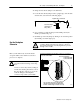
ATTENTION: Remove power from the 1771 I/O
chassis backplane and field wiring arm before
removing or installing an I/O module.
• Failure to remove power from the backplane or wir-
ing arm could cause module damage, degradation of
performance, or injury.
• Failure to remove power from the backplane could
cause injury or equipment damage due to possible
unexpected operation.
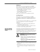
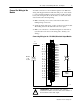
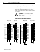
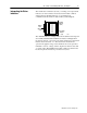
Swing the chassis locking bar down into place to secure
the modules. Make sure the locking pins engage.
1771A1B, A2B, A3B, A3B1, A4B I/O chassis
1771A1B, A2B, A3B1, A4B Series B I/O chassis
locking
tab
card guides
module
module
19809
card guides
locking bar
locking bar pin
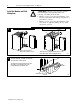
Snap the chassis latch over
the top of the module to secure it.
1
17643
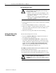
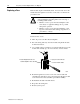
wiring arm
install
remove
horizontal bar
Attach the wiring arm (1771WN) to the horizontal
bar at the bottom of the I/O chassis.
The wiring arm pivots upward and connects with
the module so you can install or remove the
module without disconnecting the wires.
1771WN
2
Install the Module and Field
Wiring Arm