
Installation Instructions Manual

AC (120V) Isolated Output Module, 16 Outputs4
Publication
17715.21 -February 1997
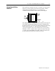
Initial Handling Procedures
!
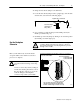
ATTENTION: Remove power from the 1771 I/O
chassis backplane and wiring arm before removing or
installing an I/O module.
• Failure to remove power from the backplane or wir-
ing arm could cause module damage, degradation of
performance, or injury.
• Failure to remove power from the backplane could
cause injury or equipment damage due to possible
unexpected operation.
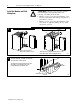
• Touch a grounded object to rid yourself of charge before handling
the module.
• Do not touch the backplane connector or connector pins.
• When you configure or replace internal components, do not touch
other circuit components inside the module. If available, use a
static-safe work station.
• When not in use, keep the module in its static-shield bag.
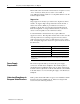
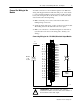
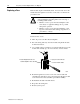
The fuse-blown jumper has two modes:
• the preset, standard (STD) mode – displays the fuse status on
the red fuse-blown status indicator
• the customer side indication (CSI) mode – displays the fuse
status in the input image table and on the red fuse-blown status
indicator. This mode configures the module as a 16 point output
module that utilizes both the output and input image data
tables of your controller. When a fuse blows, all 16 bits in the
associated input image table will turn on (1).
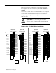
For
example,
if you install the module in a PLC5 system and address the module
as O:012, then the fuse status bits are in I:012.
To monitor the status of the module fuses, make certain that your
user program monitors the module’s input image table for ‘‘on” bits.
!
ATTENTION: Do not put the module jumper in
CSI mode when you use this module in a
complementary mode. Your system will not operate
properly.
Setting the Mode of the
FuseBlown Jumper