Installation Instructions dc (10…60V) Output Module Catalog Number 1771-OBD Series C Topic Page About This Publication 1 Important User Information 2 Before You Begin 4 Key the Backplane 5 Install the Module 6 Interpreting the LED Indicators 11 Replace the Fuse 12 Hazardous Location Approvals 13 Specifications 15 About This Publication Use this document as a guide when installing the 1771-OBD series C output module.
dc (10…60V) Output Module Important User Information Solid state equipment has operational characteristics differing from those of electromechanical equipment. Safety Guidelines for the Application, Installation and Maintenance of Solid State Controls (publication SGI-1.1 available from your local Rockwell Automation sales office or online at http://literature.rockwellautomation.com) describes some important differences between solid state equipment and hard-wired electromechanical devices.
dc (10…60V) Output Module 3 Environment and Enclosure ATTENTION This equipment is intended for use in a Pollution Degree 2 industrial environment, in overvoltage Category II applications (as defined in IEC publication 60664-1), at altitudes up to 2000 m (6562 ft) without derating. This equipment is considered Group 1, Class A industrial equipment according to IEC/CISPR Publication 11.
dc (10…60V) Output Module Before You Begin Before you begin, make sure that the following decisions are made. Determining Module Placement in the I/O Chassis You can place your module in any I/O module slot of the I/O chassis, except for the extreme left slot. This slot is reserved for programmable controllers or adapters. Group your module to minimize adverse effects from radiated electrical noise and heat.
dc (10…60V) Output Module 5 Key the Backplane Place your module in any slot in the chassis except the leftmost slot, which is reserved for processors or adapters. Position keying bands in the backplane connectors to correspond to the key slots on the module. Place the keying bands: - between 10 and 12 - between 22 and 24 I/O Chassis You can change the position of these bands if subsequent system design and rewiring makes insertion of a different type of module necessary. 1.
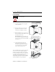
dc (10…60V) Output Module Install the Module ATTENTION Make certain that you do not install this module into a chassis slot keyed for a 1771-IAD series D input module. Install the module and secure it in the chassis. 1. Position the module in the card guides for the chosen slot. 1771-A1B, 1771-A2B, 1771-A3B, 1771-A3B1, 1771-A4B I/O Chassis Locking Tab 2. Slide the module into the chassis and apply firm, even pressure to seat the module into its backplane connector. Card Guides 3.
dc (10…60V) Output Module 7 Connect Wiring Connect your I/O devices to the field wiring arm, 1771-WH, shipped with the module. WARNING WARNING ATTENTION When you connect or disconnect the wiring arm with field-side power applied, an electrical arc can occur. This could cause an explosion in hazardous location installations. Be sure that power is removed or the area is nonhazardous before proceeding.
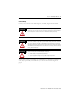
dc (10…60V) Output Module Connection Diagram See applicable codes and laws. +dc +dc +dc +dc Output 00 Output 01 Output 02 A B C D 00 Output 03 01 02 03 Output 04 04 Output 05 05 06 Output 06 Output 07 Output 10 Output 11 Output 12 07 10 11 12 Output 13 13 Output 14 14 Output 15 Output 16 15 Output 17 -dc 17 16 + dc Output Device + User dc Supply _ _ The output device is sinking current from the module. E Sourcing Configuration Actual wiring runs in this direction.
dc (10…60V) Output Module ATTENTION IMPORTANT 9 Observe proper polarity, as indicated in the connection diagram on page 10 with dc power connections. Reverse polarity, or application of ac voltage, could damage the module.
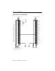
dc (10…60V) Output Module Driving an Input with an Output Module dc (10…60V) Output Module 1771-OBD dc (20…60V) Input Module 1771-ICD 22…60V dc +dc Not Used +dc Not Used +dc Not Used +dc Not Used Output 00 Input 00 Output 01 Input 01 Output 02 Input 02 Output 03 Input 03 Output 04 Input 04 Output 05 Input 05 Output 06 Input 06 Output 07 Input 07 Output 10 Input 10 Output 11 Input 11 Output 12 Input 12 Output 13 Input 13 Output 14 Input 14 Output 15 Input 15 Output
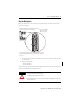
dc (10…60V) Output Module 11 Interpreting the LED Indicators The front panel of your module contains one green module active indicator, 16 red status indicators, and one red fuse blown indicator. The green module active indicator lights when the module is powered and the processor keyswitch is in RUN mode. The indicator light turns off when the processor resets the outputs.
dc (10…60V) Output Module Replace the Fuse An overload or short will cause the single onboard fuse to blow when the module output exceeds 10 A. The onboard fuse does not protect the individual output transistors. To replace the onboard fuse, do the following. 1. Turn off all power to the I/O chassis and all output device power to the field wiring arm. ATTENTION Remove power from the 1771 I/O chassis backplane and field wiring arm before removing or installing an I/O module.
dc (10…60V) Output Module 13 Hazardous Location Approvals North American Hazardous Location Approval The following information applies when operating this equipment in hazardous locations. Products marked CL I, DIV 2, GP A, B, C, D are suitable for use in Class I Division 2 Groups A, B, C, D, hazardous locations and nonhazardous locations only. Each product is supplied with markings on the rating nameplate indicating the hazardous location temperature code.
dc (10…60V) Output Module European Hazardous Location Approval European Zone 2 Certification (The following applies when the product bears the EEx Marking.) This equipment is intended for use in potentially explosive atmospheres as defined by European Union Directive 94/9/EC.
dc (10…60V) Output Module 15 Specifications dc (10…60V) Output Module, 1771-OBD Series C Attribute Value Outputs per module 16 nonisolated Module location 1771-A1B through 1771-A4B I/O chassis (Do not use this module with 1771-A4 I/O chassis) User supply voltage 10…60V dc Voltage, on-state output, nom 48V dc Current rating (see Derating Curve) 2 A per output resistive, not to exceed 8 A per module 0.
dc (10…60V) Output Module Environmental Specifications Attribute Value Temperature, operating IEC 60068-2-1 (Test Ad, Operating Cold), IEC 60068-2-2 (Test Bd, Operating Dry Heat), IEC 60068-2-14 (Test Nb, Operating Thermal Shock): 0…60 °C (32…140 °F) Temperature, storage IEC 60068-2-1 (Test Ab, Unpackaged Nonoperating Cold), IEC 60068-2-2 (Test Bb, Unpackaged Nonoperating Dry Heat), IEC 60068-2-14 (Test Na, Unpackaged Nonoperating Thermal Shock): –40…85 °C (–40…185 °F) Relative humidity IEC 6006
dc (10…60V) Output Module 17 Certifications Certification (when product is Value marked)(1) UL UL Listed Industrial Control Equipment. See UL File E65584 CSA CSA certified Process Control Equipment. See CSA file LR54689C. CSA CSA certified Process Control Equipment for Class I, Division 2, Groups A, B, C and D Hazardous locations. See CSA file LR69960C.
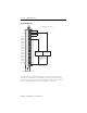
dc (10…60V) Output Module Derating Curve 9 8 Module Current - Amperes 7 6 5 4 3 2 1 0 0 10 20 30 Temperature (°C) Publication 1771-IN054C-EN-P - November 2006 40 50 60
dc (10…60V) Output Module 19 Notes: Publication 1771-IN054C-EN-P - November 2006
Rockwell Automation Support Rockwell Automation provides technical information on the Web to assist you in using its products. At http://support.rockwellautomation.com, you can find technical manuals, a knowledge base of FAQs, technical and application notes, sample code and links to software service packs, and a MySupport feature that you can customize to make the best use of these tools.