
Installation Instructions Instruction Manual

AC (120/240V) Output Module 9
Publication 1771ĆIN031B-EN-P - November 2002
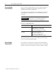
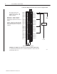
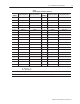
Table A
Module Output Terminal Assignments
Terminal
Number
Output Assignment I/O program address
Terminal
Number
Output Assignment I/O program address
01
1
120V ac Ć 21
1
120V ac Ć
02 Output 00 0RG00 22 Output 00 0R(G+1)00
03 Output 01 0RG01 23 Output 01 0R(G+1)01
04 Output 02 0RG02 24 Output 02 0R(G+1)02
05 Output 03 0RG03 25 Output 03 0R(G+1)03
06 Output 04 0RG04 26 Output 04 0R(G+1)04
07 Output 05 0RG05 27 Output 05 0R(G+1)05
08 Output 06 0RG06 28 Output 06 0R(G+1)06
09 Output 07 0RG07 29 Output 07 0R(G+1)07
10 N.C. Ć 30 N.C. Ć
11
1
120V ac Ć 31
1
120V ac Ć
12 Output 10 0RG10 32 Output 10 0R(G+1)10
13 Output 11 0RG11 33 Output 11 0R(G+1)11
14 Output 12 0RG12 34 Output 12 0R(G+1)12
15 Output 13 0RG13 35 Output 13 0R(G+1)13
16 Output 14 0RG14 36 Output 14 0R(G+1)14
17 Output 15 0RG15 37 Output 15 0R(G+1)15
18 Output 16 0RG16 38 Output 16 0R(G+1)16
19 Output 17 0RG17 39 Output 17 0R(G+1)17
20 N.C. Ć 40 N.C. Ć
Where: R = rack number (1, 2, 3, etc.)
G = I/O group (0 Ć 7)
G+1 = I/O group plus 1
Note: If multiple power supplies are used, do not exceed the specified isolation voltage.
1
For operating voltages greater than 120V ac, each channel group must be connected to the same operating voltage phase at L1.