
Manual

Command Initiation, Execution, and
Monitoring
Chapter 7
7-13
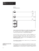
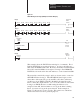
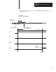
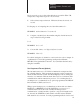
Figure 7.7
FAULT
Bit Diagnostic Rungs (Multiple Commands Example)
055
01
/
Remote Fault Status
TOF
030
0.1
055
00
/
Local Fault
Status
010
00
030
15
Timed Bit
Indicator
Output
Rung 1
Rung 3
Rung 4
055
00
033
07
/
033
06
/
033
05
/
033 04
/
033 03
/
033 02
/
033 01
/
033 00
/
Status
Local Fault
Rung 2
055
01
033
17
/
033
16
/
033
15
/
033 14
/
033 13
/
033 12
/
03311
/
033 10
/
Status
Remote Fault
PR 020
AC 000
This example shows the FAULT bit monitoring for 8 commands. The 8
LOCAL FAULT bits are monitored in rung 1. As long as all 8 bits are
OFF, status bit 05500 remains ON. However, should any LOCAL FAULT
bit be ON, status bit 05500 is de-energized. In rung 2, the 8 REMOTE
FAULT bits are monitored in the same manner, to control status bit 05501.
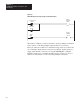
The status bits controlled by rungs 1 and 2 are, in turn, used to control an
OFF-DELAY timer in rung 3. The OFF-DELAY timer begins to time
when either of the status bits goes from OFF to ON, that is, when rung
conditions go from TRUE to FALSE. Bit 03015, the timed bit of the
timer, controls the output indicator. As soon as the conditions of the timer
in rung 3 are TRUE, this bit is set ON causing the indicator to be
energized. Once ON, this bit remains on as long as the timer is timing,
that is, for at least as long as the preset interval. In the example of
Figure 7.7, this preset is set at 2 seconds. This value is not critical but
should exceed 0.5 seconds for practical purposes.