
Manual


Communication Zone Rungs
Chapter 5
5-2
Overall Format
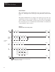
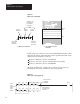
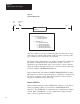
The overall format for the communication zone of program is shown in
Figure 5.1. This figure shows each type of rung that can be entered in this
zone.
The actual communication zone rungs for any station processor may vary
significantly from those shown in Figure 5.1. The length of this program
area is a function of the number of remote stations processors with which
the local station processor communicates and the number of transmissions
of data with these remote stations.
Figure 5.1
Communication
Zone Format (general)
Start
011
[
G
]
077
[
G
]
015
[
G
]
(
L
02707
OFF
)
020
[
G
]
070
[
G
]
076
[
G
]
017
[
G
]
022
[
G
]
022
[
G
]
(
02707
)
017
[
G
]
063
[
G
]
065
[
G
]
010
[
G
]
060
[
G
]
062
[
G
]
03210 02000 016
[
G
]
022
[
G
]
024
[
G
]
(
02707
)
[][]
03211 01702 12000
12001 12002
(
02707
)
[][]
12003
[][][]
[]
12004 12005 12006
12007
[][][]
[]
12010 12011 13511
12600
[][][]
[]
(
02707
)
U
Header
Memory
Read/
Bit
Delimiter
Rung
Access
Rung
Write
Write
Rung
Command
Rungs
Header and delimiter rungs are required for each
station processor. Memory access and command rungs
are programmed as needed.
1
1
1