
Manual

Commands
Chapter 4
4-12
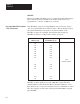
The addressing scheme is summarized in this chart:
T
able 4.A
Internal
Addressing of a PLC-4 Microtrol Controller
T
ype of
Address
Controller
I.D.
Bit
Address Range
I=Input 1-8 01-20
O=Output 1-8 01-12
X=Flags 1-8
01-32
(1)
S=Stores 1-8 01-99
T
ype of
Address
Controller
I.D.
Timer/Counter
Number
Bit
Description
T = T
imer 1-8 01-32
15 - T
imer Clock
16 - Enable
31 - T
imer T
iming
32 - Done
C = Counter
1-8 01-32
15 - Count -Down Enable
16 - Count-Up Enable
31 - Overflow Underflow
32 - Done
(1)
Flag bits 31 and 32 have a special significance. See the PLC-4 Microtrol Product Guide
(publication 1773-800).
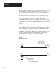
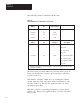
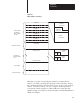
The memory map for a PLC-4 Microtrol controller, ID #1, shown in
Figure 4.4, includes data on inputs, outputs and flags of each active
controller on the loop.
Each member of the PLC-4 Microtrol loop, including the interface
module, shares the status of the input, output, and flag bits for each
controller on the loop. This becomes significant when you want to
determine response time.
Each time you enter a non-privileged command, you must enter an
address code. This becomes significant when you want to determine
response time.