
Manual


Start–up and Troubleshooting
Chapter 9
9-19
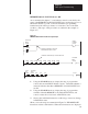
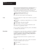
REMOTE/LOCAL FAULT Indicator ON
As recommended in chapter 7, some indicator must be controlled by the
status of the REMOTE and LOCAL FAULT bits at each station processor.
Should this indicator go ON, connect and initialize a programming
terminal and follow these procedures to isolate the source of the fault
condition. (The steps of this procedure are outlined in the example of
Figure 9.7.)
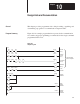
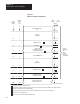
Figure 9.7
REMOTE/LOCAL
F
AUL
T T
roubleshooting Example
055
01
/
L
010
00
055
00
/
Local Fault
Status
Indicator
Output
Instruction intensified. Thus Local
Fault Status Bit, 05500, is OFF.
055
00
032
00
/
032
01
/
032
02
/
03203
/
03204
/
03205
/
03206
/
032 07
/
Status
Local Fault
Instruction normal intensity. Thus this bit is ON.
OFF
02707
03112
023 00
052
000
G
020
000
G
022
000
G
Bit
Start
Code
Command
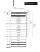
1. Using the SEARCH functions, display the rung of program that
controls the external FAULT indicator device. Determine whether a
status bit indicates that either a REMOTE or LOCAL FAULT bit is
set ON.
2. Using the SEARCH functions, display the rung of program that
examines either the REMOTE or the LOCAL FAULT bits, and
controls a status bit or bits based on FAULT bit states.
3. Observe the individual instructions of this rung to detect any change
in FAULT bit status.
When you use the rungs recommended in Figure 7.6, EXAMINE OFF
instructions address each fault bit. When these instructions are displayed