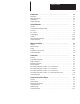
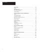
Table of Contents Introduction . . . . . . . . . . . . . . . . . . . . . . . . . . . . . . . . . . . . . . 1-1 Description . . . . . . . . . . . . . . . . . . . . . . . . . . . . . . . . . . . . . . . . . . . . . . . . About This Manual . . . . . . . . . . . . . . . . . . . . . . . . . . . . . . . . . . . . . . . . . . . Organization . . . . . . . . . . . . . . . . . . . . . . . . . . . . . . . . . . . . . . . . . . . . . . . Chapter Summary . . . . . . . . . . . . . . . . . . . . . . . . . . . . . . . .
Table of Contents Status Words . . . . . . . . . . . . . . . . . . . . . . . . . . . . . . . . . . . . . 6-1 General . . . . . . . . . . . . . . . . . . . . . . . . . . . . . . . . . . . . . . . . . . . . . . . . . . START/DONE Word . . . . . . . . . . . . . . . . . . . . . . . . . . . . . . . . . . . . . . . . . REMOTE/LOCAL FAULT Word . . . . . . . . . . . . . . . . . . . . . . . . . . . . . . . . . . Error Code Storage Word . . . . . . . . . . . . . . . . . . . . . . . . . . . . . . . . . . . . . .
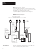
Chapter 1 Introduction Description An Allen-Bradley Data Highway extends the capabilities of programmable controllers by letting them exchange data with each other and with other intelligent RS-232-C devices. Data Highway integrates individual controllers into a larger automated manufacturing network. On a single Data Highway cable, as many as 64 separate programmable controllers and computers can be connected over a distance of 10,000 feet (3,048m).
Chapter 1 Introduction Mini-PLC-2/15 (cat. no. 1772-LV) This module enables communication of memory data between these processors, and from any of these processors to other processors on the Data Highway via communication adapter modules. A typical Data Highway configuration is shown in Figure 1.2. Figure 1.2 Representative Data Highway Configuration 10,000 feet (3,048 meters) maximum Data Highway Cable Trunkline 1770-SC Station Connector Cable Droplines 100 feet (30.
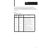
Chapter 1 Introduction This manual describes installation, operation, and programming necessary to use the KA2 communication adapter module. Use this manual with the other manuals and publications pertinent to your system. Table 1.A lists other available Data Highway manuals and Table 1.B lists PC manuals. Table 1.A Data Highway Documentation Old Publication Number New Publication Number 1774-819 1774-6.5.8 User’s Manual, Communication Adapter Module (cat. no. 1771-KA) 1771-822 1771-6.5.
Chapter 1 Introduction Table 1.B Manuals for Allen-Bradley Programmable Controllers Controller Old Number New Number Mini-PLC-2 Program. Cont. 1772-820 1772-821 1772-6.6.3 1772-6.8.4 Assembly and Installation Programming and Operation Mini-PLC-2/05 1772-830 1772-831 1772--6.6.6 1772-6.8.6 Assembly and Installation Programming and Operations Mini-PLC-2/15 Program. Cont. 1772-803 1772-804 1772-6.6.1 1774-6.8.2 Assembly and Installation Programming and Operations PLC-2/20 Program. Cont.
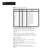
Chapter 1 Introduction Controls communication without need for a host computer. Has automatic error checking of data it receives. Has self-checking diagnostics. Shows status and diagnostics with LED indicators and error codes. Controls DONE and REMOTE/LOCAL FAULT memory bits as status and diagnostic indicators. Automatically re-tries messages. Automatically recovers from master station fault condition. Has selectable priority levels for commands. Is compatible with industrial terminal system.
Chapter 1 Introduction 1–6
Chapter 2 Station Hardware General The following components make up a Data Highway station with a PLC-2 family PC: Communication Adapter Module Processor PLC-2 I/O adapter module for PLC-2/20 and PLC-2/30 processors Bulletin 1771 I/O chassis Power supply Data Highway/Processor cable Data Highway cable dropline Figure 2.1 shows the configuration of a typical Data Highway station for PLC-2/20 and PLC-2/30 processors. Figure 2.2 shows a typical configuration for the mini-processor module. Figure 2.
Chapter 2 Station Hardware Figure 2.2 Typical Station Configuration--Mini-PLC-2, Mini-PLC-2/05, and Mini-PLC-2/15 Controllers Data Highway Cable Trunkline Station Mini-Processor Module (cat. no. 1772-LV, -LS, -LSP; 1772-LN1, -LN2, -LN3) Station Dropline System Power Supply Connection for Programming Terminal Data Highway Processor Cable (cat. no. 1771-CN.-CO) Communication Adapter Module (cat. no.
Chapter 2 Station Hardware connection, switches for enabling or disabling specific module operations, and indicators to aid in monitoring module behavior and in troubleshooting. Subsequent sections describe each of these parts of the module and other aspects of module hardware that are significant in its set-up and installation. Each communication adapter module in a Data Highway installation must have a unique station number.
Chapter 2 Station Hardware Figure 2.4 Module Connection Summary Data Highway Cable (User-Assembled) Program Panel Interconnect Cable (Cat. no. 1772-TC) “Program Panel” or “Interface” Socket on Processor Data Highway Processor Cable (cat.no. 1771-CN, -CO, -CR) Industrial Terminal System (cat. no. 1770-T1 and T2) 10863-I Data Highway Connector The upper connector of the module accepts the 15-pin Data Highway dropline cable.
Chapter 2 Station Hardware To connect any programming terminal to the PROGRAM INTERFACE connector, use a program panel interconnect cable (cat. no. 1772-TC). With a 1772-KA2 module installed, the PROGRAM INTERFACE connector substitutes for the PROGRAM PANEL connector on PLC-2/20 or PLC-2/30 processors or the INTERFACE socket on the Mini-PLC-2, Mini-PLC-2/05, or Mini-PLC-2/15.
Chapter 2 Station Hardware Figure 2.5 Module Indicators COMM ADAPTER Transmitting Receiving Message Ready Program Status Processor Link Status XMTG RCVG RDY PROG PROC XMTG The green transmitting indicator turns on when the module is current master of the Data Highway. When this indicator is on, therefore, the communication adapter module is transmitting messages on the Data Highway communication link, or it is polling.
Chapter 2 Station Hardware PROG The red program status indicator tells you the status of module checks on the communication zone rungs of the user program. (The section titled “Overall Format,” chapter 5, describes these rungs.) The module first checks these rungs at power-up. When it locates the header rung of this zone, the module turns the PROG indicator on. After it checks the rungs, provided no errors are found, the module turns the PROG indicator OFF.
Chapter 2 Station Hardware Module Specification Summary Table 2.A lists operating specifications for a 1771-KA2 module. Table 2.A Operating Specifications Function • Interface entire PLC-2 family programmable controller to the Data Highway Compatible Power Supplies • System power supply (cat. no. 1771-P1) • Auxiliary power supply (cat. no. 1772-P2) Location • Bulletin 1771 I/O Chassis (any slot except furthest left) • System power supply module (cat. no.
Chapter 2 Station Hardware The interaction between a KA2 module and its station processor occurs in memory control. The station KA2 can read data from and write data into processor memory, based on various user-programmed commands. Commands that originate at a station communication adapter module can control only data table areas of processor memory. Commands generated by a computer that is connected to the Data Highway through a communication controller module (cat. no.
Chapter 2 Station Hardware Figure 2.6 1771-AL Adapter Module PLC-2 I/O ADAPTER 10864-I Power Supply A 1771-KA2 module gets its power from the backplane. It requires +5V DC at 1.2 amperes (max.). The following power supplies are compatible: System power supply (cat. no. 1771-P1) Auxiliary power supply (cat. no. 1771-P2) PLC-2 system power supply module (cat. no. 1772-P1, series B or later) PLC-2 auxiliary power supply (cat. no. 1777-P2, and 1777-P4 series B or later) Modular power supplies (cat. no.
Chapter 2 Station Hardware Figure 2.7 1771-P1 System Power Supply Battery Low DC ON ALLEN-BRADLEY 10865-I When using the PLC-2/20 or PLC-2/30 processor, any of these supplies can power the I/O chassis so long as core memory is not being used. (Refer to processor manuals.) An auxiliary power supply (cat. no. 1771-P2) closely resembles the system power supply shown in Figure 2.7. PLC-2 power supply module (cat. no.
Chapter 2 Station Hardware Figure 2.8 PLC-2 Power Supplies PLC 2/30 AC FUSE 10236-I a. PLC-2 System Power Supply Module AC FUSE 10236a-I b.
Chapter 2 Station Hardware Cables A 1771-KA2 module requires the following cables for installation: Data Highway/Processor cable (cat. no. 1771-CN,-CO,-CR) User-assembled Data Highway cable Figure 2.1 and Figure 2.2 show the connections made with these cables. You can order Data Highway/Processor cables in 3 lengths: 1.5 ft. (cat. no. 1771-CN) 3.5 ft. (cat. no. 1771-CO) 10.5 ft. (cat. no. 1771-CR) The 2 shorter cables are intended for connection to a Mini-PLC-2, Mini-PLC-2/05, or Mini-PLC-2/15 module.
Chapter 2 Station Hardware 2-14
Chapter 3 Module Installation General This chapter outlines procedures for preparation, installation, and connection of a 1771–KA2 module. Before performing these procedures, you should check component compatibility and the station set–up recommendations in chapter 2. Switch Settings There are 3 sets of switches on a 1771–KA2 circuit board: Write option switch assembly Station no. switch group Data Highway baud rate switch assembly Refer to Figure 3.1.
Chapter 3 Module Installation Use the tip of a ball–point or other pointed instrument to set these switches. Do not use a pencil, as lead could jam the switch. For troubleshooting purposes, we recommend that the programmer document the required switch settings for each 1771–KA2. Use form 5030, in chapter 10, to record switch settings for the module at each station. That way, should replacement of the module be required, switches on the replacements can be set quickly.
Chapter 3 Module Installation ON – Enables execution of received protected commands. OFF – Disables received protected commands. Note that both an ON setting of this switch and a memory access rung are required to allow execution of received protected commands. (Memory Access rungs are described in chapter 5.) This switch does not prevent the module from receiving and executing unprotected commands from another station.
Chapter 3 Module Installation RECEIVE PRIVILEGED WRITE SWITCH Switch 4 determines whether the module can execute received privileged write commands. These commands can be issued only from a computer connected through a communication controller module (cat. no. 1771–KE/KF). These commands give the computer the capability to alter the user program memory of the station processor.
Chapter 3 Module Installation The station number switch group comprises 3 switch assemblies (SW2, SW3, SW4) on the module circuit board, as Figure 3.3 indicates. These switches determine the station number of each communication adapter module. The station number is a 3–digit octal number from 0108–0778 or 1108–3768. Each of the 3 switch assemblies in this group is set to represent an individual digit of this station number. Figure 3.3 shows the combination of switch settings for each digit. Figure 3.
Chapter 3 Module Installation In this binary–coded octal numbering arrangement, each switch has an associated binary value: 1, 2, or 4 if set ON, 0 if set OFF. The value of each individual digit of the station number is the sum of the binary values in its corresponding switch assembly. Table 3.A gives an example for the settings of this switch group. Table 3.A Switch Setting Example: Station No. 037 STATION NO. DIGITS SWITCH NO.
Chapter 3 Module Installation The module is shipped with these switches set for 57.6K baud. Both switches are set ON for this communication rate. This baud rate is the intended Data Highway communication rate. CAUTION: Do not set these switches for any other baud rate. Incorrect setting of these switches may cause faulted data transmission on the Data Highway communication link. This may disable Data Highway operation until the switch setting is corrected.
Chapter 3 Module Installation Figure 3.5 Keying Band Position ÉÉ ÉÉ Keying Bands Installation In The I/O Slot 2 4 6 8 10 12 14 16 18 20 22 24 26 28 30 32 34 36 ÉÉ ÉÉ ÉÉ ÉÉ Follow these procedures to install the module: 1. Turn I/O chassis power off. (This refers to the power supply that connects to the I/O chassis at its backplane. CAUTION: To avoid module damage, always be certain that power to the I/O chassis is off before insertion or removal of the KA2. 3-8 2.
Chapter 3 Module Installation Cable Connections The following cable connections are made to a communication adapter module: Data Highway cable Program panel interconnect cable (cat. no. 1772–TC) Data Highway/Processor cable (cat. no. 1771–CR, –CO,–CN) At set up, all cable connections to the module can be made with power on. After the program is up and running, however, it is safer to make connections with power off because of the possibility of noise that connecting will make.
Chapter 3 Module Installation Figure 3.6 Data Highway Cable Connection Trunkline 1770–SC Station Connector Dropline (100 feet maximum) Communication Adapter Module (cat. no. 1771–KA2) Program Panel Interconnect Cable Connection The center connector of the communication adapter module is labeled PROGRAM INTERFACE. When the module is installed and connected to the processor, this socket connects an industrial terminal system (cat. no. 1770–T1, –T3).
Chapter 3 Module Installation Figure 3.7 Industrial Terminal Connection ÄÄ ÄÄ ÄÄ Channel A Program Panel Interconnect Cable (cat. no. 1772-TC) 10219a-I Data Highway/Processor Cable Connector The bottom connector of a 1771–KA2 module is labeled PROCESSOR. The communication module communicates with the station processor through this connector. The Data Highway/Processor cable (cat. no. 1771–CN, –CO, –CR) connects from this socket to a socket on the fact of the station processor.
Chapter 3 Module Installation Figure 3.8 Data Highway/Processor Cable Connection PLC-2/20 Processor Communication Adapter Module (cat.no. 1771-KA2) PLC 2/20 Connector Labeled “Program Panel” AC FUSE Processor Connector Data Highway Processor Cable (cat.no. 1771-CR) a. Connection to PLC-2/20 or PLC-2/30 Processor Mini-PLC-2/15 Module Connector Labeled “Interface” Communication Adapter Module (cat.no. 1771-KA2) Data Highway Processor Cable (cat.no. 1771-CN, -CO) Processor Connector b.
Chapter 4 Commands General The primary function of a KA2 module is to transfer data to and from its station processor. The module is instructed to transfer specific units of data by user-programmed commands. The communication adapter module transmits and receives the following set of non-privileged commands: Protected write Protected bit write Unprotected write Unprotected bit write Read These commands are of three general types: write, bit write, and read. (Refer to Figure 4.1).
Chapter 4 Commands Privileged Commands This chapter describes functions of these commands and their access to data table locations at station processors. A KA2 module can also receive privileged commands from a computer or another intelligent RS-232-C device through a 1771-KE/KF communication controller module. These privileged commands and their functions (briefly) include: Diagnostic counters reset - resets to zero all diagnostic timers & counters in the station interface module.
Chapter 4 Commands Terminology: Remote/Local Station In this and later chapters, we use the terms “remote station” or “local station.” The local station is the point of reference. When describing the commands, for instance, the local station is the one sending the command. A remote station is any station that receives a command from the local station. Figure 4.1 illustrates this terminology. Protected/Unprotected Each 1771-KA2 module command has a prefix, either “protected” or “unprotected.
Chapter 4 Commands Figure 4.2 Protected/Unprotected Command Distinction Memory Word Address 021 022 023 > An unprotected command can access any area of data table memeory at a receiving station processor End of Data Table ÉÉÉÉÉÉÉÉÉ ÉÉÉÉÉÉÉÉÉ ÉÉÉÉÉÉÉÉÉ ÉÉÉÉÉÉÉÉÉ ÉÉÉÉÉÉÉÉÉ ÉÉÉÉÉÉÉÉÉ ÉÉÉÉÉÉÉÉÉ ÉÉÉÉÉÉÉÉÉ ÉÉÉÉÉÉÉÉÉ ÉÉÉÉÉÉÉÉÉ ÉÉÉÉÉÉÉÉÉ ÉÉÉÉÉÉÉÉÉ a.
Chapter 4 Commands A write command can control data table words at any station processor. However, certain data table areas at each type of processor have a special function and should not be controlled by write commands. (Sections titled “Accessible Data Table Locations-PLC-2 Processors” and “Accessible Data Table Locations-PLC Processors” cover data table control.) Bit Write Commands Bit write commands control the ON/OFF status of bits in a remote station data table.
Chapter 4 Commands This first restriction simply states that no bit should be directly controlled, that is, addressed, by both an output instruction at its local station processor and a bit write command from some remote station processor. Bit write commands are generally used to set storage bits in a station processor data table. These storage bits may then be examined in the user program as conditions to energize an output bit.
Chapter 4 Commands The second restriction listed above applies when the destination station is a PLC-2 family PC. For these processors, when the station communication adapter module receives a bit write command it manipulates the 8-bit byte of the 16-bit memory word in which the addressed bit is located. (This may be the low byte, containing bits 00-07, or the high byte, containing bits 10-17.
Chapter 4 Commands Processor work areas Input image table Word 027 Later paragraphs describe the limitations in controlling each of these areas. Access to all other data table areas is subject to the requirements of the programmer. Processor Work Areas The processor work areas for PLC-2 family processors are addresses 000-007 and 100-107. These areas are used for specific processor functions and are not accessible to commands from a station communication adapter module.
Chapter 4 Commands indicates a low-battery condition. Because of these special functions, care must be exercised in controlling word 027 with a write or bit write command. The processor does not prevent data from being written to this data table word. Accessible Data Table Locations When it executes a read, write, or bit write command, the communication - PLC Processors adapter module controls data table locations at a station processor.
Chapter 4 Commands Word 000 Reserve word 000 of the PLC processor output image table when using a KA2. This means that commands from another station must not be programmed to control word 000 or any of its bits. Accessible Data Table Locations Each PLC/PLC-2 station on a Data Highway can read from or write to - PLC-3 Processors only one specific buffer file at a PLC-3 station. That is the PLC-3 input file with a number that corresponds to the station number of the PLC/PLC-2 station.
Chapter 4 Commands The PLC/PLC-2 station can use either protected or unprotected commands to access its assigned PLC-3 file. Note, however, that the PLC/PLC-2 station cannot access its assigned file until you create and allocate that file. To create a PLC-3 file, use the CREATE command described in the PLC-3 Programming Manual (publication 1775-6.4.1).
Chapter 4 Commands The addressing scheme is summarized in this chart: Table 4.A Internal Addressing of a PLC-4 Microtrol Controller Type of Address Controller I.D. Bit Address Range I=Input 1-8 01-20 O=Output 1-8 01-12 X=Flags 1-8 01-32 (1) S=Stores 1-8 01-99 Type of Address Controller I.D.
Chapter 4 Commands Figure 4.
Chapter 4 Commands address code 010 addresses the first controller - controller 1 - while address code 011 addresses the second controller - controller 2. A PLC-4 Microtrol uses a decimal addressing scheme (Table 4.A). The PLC-2 family of programmable controllers use an octal addressing scheme. Thus, you must convert the PLC-4 Microtrol’s decimal addresses to octal. Address codes are divided into four sets: 1. store words 2. input, output, and flag words 3. input, output and flag area 4.
Chapter 4 Commands Chapter Summary This chapter told you about the 1771-KA2’s: Station terminology Commands, protected and unprotected, reads & writes Processors’ input image table addresses, locations In chapter 5 you will learn about rungs, codes, and more commands.
Chapter 4 Commands 4-16
Chapter 5 Communication Zone Rungs General At the beginning of the ladder-diagram program, you enter a special set of rungs that dictate communication adapter module activity. The KA2 scans this set of rungs at power-up for operating information. WARNING: Do not make on-line edits of the communication zone.
Chapter 5 Communication Zone Rungs Overall Format The overall format for the communication zone of program is shown in Figure 5.1. This figure shows each type of rung that can be entered in this zone. The actual communication zone rungs for any station processor may vary significantly from those shown in Figure 5.1.
Chapter 5 Communication Zone Rungs The order of these communication zone rungs is as follows: 1. Header rung 2. Memory access rung(s) (as needed) 3. Command rung(s) (as needed) 4. Delimiter rung These rungs must always appear in this order at the beginning of the ladder diagram program. If you are using two KA2 modules, or a combination of KA2 and -KG modules with the same processor, enter one immediately after the other.
Chapter 5 Communication Zone Rungs Figure 5.2 Header Rung Local Station Number Address of Error Code Storage Word 011 [G ] 000 077 [G ] 000 Timeout Preset Code 015 [G ] 000 02707 ( L ) OFF The 3 GET instructions in the header rung list the following: Local station number Address of ERROR CODE storage word Timeout preset code The local station number is a 3-digit number switch-selected on the 1771-KA2 module. This is an octal number from 0108 to 0778 or from 1108 to 3768.
Chapter 5 Communication Zone Rungs (Note that memory access rungs are not needed to allow unprotected commands; only protected commands require a memory access rung.) A memory access rung is composed of one or more memory access branches, as shown in Figure 5.3.A. In this format, a BRANCH START precedes a group of 3 GET instructions. The first GET instruction address is the station number of a remote station.
Chapter 5 Communication Zone Rungs Figure 5.3 Memory Access Example Area Accessible to Protected Commands From Remote Station No. 010 Memory Access Boundaries in Local Station Data Table Remote Station No.
Chapter 5 Communication Zone Rungs For practical reasons, do not exceed the display area of the programming terminal when entering these rungs. You can program more than one memory access rung if needed. Note, however, that should multiple memory access rungs be required, you must enter them in succession in the communication zone, immediately following the header rung and before any command rung. Command Rungs The command rungs direct the data transfer operations of the communication adapter module.
Chapter 5 Communication Zone Rungs Figure 5.5 Command Rung Format Command Code Start Bit [ ] AAAPX [ ] REFER TO FIGURES 5.6 AND 5.7 02707 ( ) AAA – REMOTE STATION NO. P – PRIORITY INDICATOR 1 = PRIORITY MESSAGE 0 = NORMAL MESSAGE X – COMMAND TYPE 0 = PROTECTED WRITE 1 = UNPROTECTED READ 2 = PROTECTED BIT WRITE 3 = UNPROTECTED WRITE 4 = UNPROTECTED BIT WRITE After the command code, the command rung then lists the memory areas affected by the command.
Chapter 5 Communication Zone Rungs The START bit is controlled by the program. This allows a command to be initiated only when necessary. (Programming methods for START bit control are given in chapter 7.
Chapter 5 Communication Zone Rungs This format uses 3 GET statements. The address position of the first GET statement lists a remote station data table word. The specified command operation begins at this memory location. The second and third GET statements define the starting and ending boundaries of the data table words in the local station processor. These words are the beginning and ending data table locations for the words to be transferred in the write or read operation.
Chapter 5 Communication Zone Rungs Figure 5.7 Bit Command Format Area May Contain Any Legal Combination Of These Instructions: . . . Start Bit / Command Code EEEEE Branch Start (If Needed) HHH HH FFFFF / GGGGG / IIIII / JJJ JJ 027 07 Legend: EEEEE –] [– Set bit EEEEE in remote station data table on FFFFF –] / [– Set bit FFFFF in remote station data table off This format uses EXAMINE elements that address bits in the remote station processor.
Chapter 5 Communication Zone Rungs Figure 5.8 Delimiter Rung 027 07 U Chapter Summary Chapter 5 was the RUNG chapter; it discussed: Communication zone rungs Communication zone of program Header rungs Memory access rungs Command rungs Start bit, command code and word command format Bit command format with EXAMINE ON, EXAMINE OFF elements In chapter 6 you will read about bit storage, fault words, and error codes.
Chapter 6 Status Words General A 1771-KA2 communication adapter module controls certain data table words specified in the local station processor by the programmer. These data table words indicate the status of command execution and provide various types of diagnostic information for start-up and troubleshooting. These locations are: One or more pairs of adjacent words for START/DONE and REMOTE/LOCAL FAULT bit storage An ERROR CODE storage word Refer to Figure 6.1.
Chapter 6 Status Words Any accessible data table words can be used as status words in the station processor. Note that the same recommendations for data table control given in section titled “Accessible Data Table Locations - PLC-2 Processors,” chapter 4, should be followed when selecting status words. That is, processor work areas, input image table words and word 027 should not be used as status words.
Chapter 6 Status Words REMOTE/LOCAL FAULT Word As Figure 6.1 shows, the selection of a START bit in the program not only causes a corresponding DONE bit to be controlled in the same word, but also causes REMOTE and LOCAL FAULT bits to be controlled in the next data table word. A REMOTE FAULT and LOCAL FAULT bit are controlled for each command. For a command, the position of each of these FAULT bits within their respective bytes corresponds directly to the position of START and DONE bits for that command.
Chapter 6 Status Words REMOTE FAULT bits are in the upper byte of this word. A REMOTE FAULT bit is set ON when a command is received at a remote station but cannot be executed by the remote station. This may mean one of the following: Remote station processor has detected a fault in its own operation or has shut down. Remote station processor has power OFF. Remote station processor has mode select switch in PROGRAM LOAD (or PROG) mode.
Chapter 6 Status Words Error Code Storage Word When a command cannot be carried out due to a user programming error or a discrepancy in data handled by the communication adapter module, an ERROR CODE may be written into a data table memory word. The programmer selects the error code storage word and lists it in the header rung of the communication zone of program. This word stores the most recent error code written by the KA2. Figure 6.3 shows the structure of the ERROR CODE storage word.
Chapter 6 Status Words The upper byte of the ERROR CODE storage word (bits 10-17) stores a 2-digit BCD value. This value gives supplemental error or fault information, depending on the type of ERROR CODE displayed. It may have one of two meanings: Reference number Counter For ERROR CODES 01-29, the upper byte stores a 2-digit reference number. This number points to the location of a programming error within the communication zone of program.
Chapter 6 Status Words Chapter Summary This was the WORD and CODE chapter and it discussed: START/DONE, REMOTE/LOCAL FAULT bit storage REMOTE/LOCAL fault word Error code storage word (Error code list is in Appendix A.) Chapter 7 continues discussion about command initiation, control bits, fault words, and monitoring.
Chapter 6 Status Words 6-8
Chapter 7 Command Initiation, Execution, and Monitoring General This chapter describes the support programming for commands at each station processor. This programming uses the START/DONE and REMOTE/LOCAL FAULT bits, described in chapter 6, to initiate and monitor command execution. Using these recommended techniques, the programmer coordinates communication zone programming with his application program.
Chapter 7 Command Initiation, Execution, and Monitoring Figure 7.1 shows the timing of START and DONE bits for a command. The significance of START/DONE bit status is summarized in Table 7.A. Figure 7.
Chapter 7 Command Initiation, Execution, and Monitoring Faulty Operation Certain fault conditions can prevent normal reception and execution of commands by the receiving station. To indicate the source of such fault conditions, the KA2 controls REMOTE and LOCAL FAULT bits at the station processor. In general, the LOCAL FAULT bit indicates that the local station cannot confirm delivery of a command to the remote station.
Chapter 7 Command Initiation, Execution, and Monitoring Recall that the START bit is program-controlled. The REMOTE/LOCAL FAULT bits, meanwhile, are controlled by the 1771-KA2 module. The programmer must keep this relationship in mind when planning START bit control and FAULT bit monitoring in the ladder-diagram program. Note from Figure 7.2 that the FAULT bit, once ON, remains ON until the START bit is reset (turned OFF).
Chapter 7 Command Initiation, Execution, and Monitoring Thus, the rung used to UNLATCH the START bit examines these three possible responses in parallel branches of the ladder diagram program. Section titled “ON/OFF Input Status,” “Transition,” and “Timed” describe the most commonly used forms of START bit control. Each section describes a different method for initiating command execution; all examples show how the program uses both DONE and FAULT bits to UNLATCH the START bit.
Chapter 7 Command Initiation, Execution, and Monitoring Figure 7.3 Status-Initiated Command Input 11111 Done 03202 Remote Fault 03312 / Input 11111 / Local Fault 03302 / Start 032 12 L Start 032 12 U Local Fault 03302 Remote Fault 03312 In this example, the first rung is programmed to LATCH the START bit when the input, bit 11111, is ON, provided that both FAULT bits are OFF. The second rung is programmed to UNLATCH the START bit based on the response of the communication adapter module.
Chapter 7 Command Initiation, Execution, and Monitoring Even though the FAULT bits are continually reset with this method, their usefulness must not be overlooked. The section titled “REMOTE/FAULT Bit Monitoring” outlines a useful method to monitor FAULT bits and control an output indicator based on FAULT bit status. In some applications, it may be useful to send a command continuously between stations. With the example of Figure 7.
Chapter 7 Command Initiation, Execution, and Monitoring Figure 7.
Chapter 7 Command Initiation, Execution, and Monitoring In this example, a storage bit, called the “transition” bit, is manipulated to control the sending of the command. This bit is LATCHED whenever a transition of input 11111 is detected, UNLATCHED only when the DONE bit is set ON. A “compare” bit, 01111 in this example, is used to manipulate the transition bit. In rung 2, the compare bit is controlled to match the ON/OFF status of the input.
Chapter 7 Command Initiation, Execution, and Monitoring Figure 7.5 Timer-Initiated Command Done 032 02 / 046 TON 1.0 PR 010 AC 000 Timed Bit 046 15 Start 032 12 L Done 032 02 Start 032 12 U Local Fault 033 02 Remote Fault 033 12 In this example, timed bit 04615 is used to initiate the command at every preset interval, 10 seconds. This bit is examined to LATCH the START bit. The DONE, LOCAL FAULT, and REMOTE FAULT bit are examined in parallel branches to UNLATCH the START bit.
Chapter 7 Command Initiation, Execution, and Monitoring executed, but also point to the general type of fault condition that prevented command completion. The user program must monitor the REMOTE and LOCAL FAULT bits for each command. The recommendations of this section describe two methods for monitoring FAULT bits and using these bits to signal a fault condition.
Chapter 7 Command Initiation, Execution, and Monitoring Figure 7.6 FAULT Bit Diagnostic Rungs (Single Command Example) Remote Fault 03310 Output Indicator 01000 L OFF Local Fault 033 00 Done 03200 Output Indicator 010 00 U The method of Figure 7.6 can be extended to monitor multiple commands from a station, controlling multiple output indicators as necessary. However, where more than one command is being sent from a station, the use of multiple output indicators may not be practical.
Chapter 7 Command Initiation, Execution, and Monitoring Figure 7.7 FAULT Bit Diagnostic Rungs (Multiple Commands Example) Rung 1 033 07 / 033 06 / 033 05 / 033 04 / 033 03 / 033 02 / 033 01 / 033 00 / Rung 2 033 17 / 033 16 / 033 15 / 033 14 / 033 13 / 033 12 / 033 11 / 033 10 / Local Fault Status 055 00 Remote Fault Status 055 01 Rung 3 Local Fault Status 055 00 / Remote Fault Status 055 01 / Rung 4 Timed Bit 030 15 030 TOF 0.
Chapter 7 Command Initiation, Execution, and Monitoring The OFF-DELAY timer is useful in this application because it is continually reset when its rung conditions go TRUE. This means that the timed bit, 03015, remains on for as long as any FAULT bit is changing state during programmed re-tries. This keeps the output indicator on until after the DONE bit indicates command completion. NOTE: Using the rungs of Figure 7.
Chapter 7 Command Initiation, Execution, and Monitoring enters the value 37 in the lower byte of the ERROR CODE storage word of the header rung. Figure 7.
Chapter 7 Command Initiation, Execution, and Monitoring Timeout preset monitoring is intended as a backup for the other communication monitoring functions of the module. It is designed to signal any condition where the module has not completed its communication with another station or detected some fault condition within a short time. Because this timer is primarily intended as a backup for some LOCAL FAULT type of situation, its preset value is not critical.
Chapter 7 Command Initiation, Execution, and Monitoring If it is necessary to use a value other than those provided in Table 7.B, compute the 3-digit timeout preset code as follows: 1. Select a timeout preset interval. This interval must be at least one second. For the purpose of computing the code, label this number “S.” EXAMPLE: desired interval = 7 seconds = S 2. Compute a decimal (base 10) number using the desired interval of step 1 in the following formula: S+8 EXAMPLE: S + 8 = 15 3.
Chapter 7 Command Initiation, Execution, and Monitoring to detect such a condition; the simplest of these methods uses an ON-DELAY timer. Figure 7.9 shows typical rungs that can be programmed for this purpose. Figure 7.9 Typical User-Programmed Timeout Start 032 12 Done 032 02 / Remote Fault 033 12 / 060 TON 0.
Chapter 7 Command Initiation, Execution, and Monitoring communication adapter module. (REMOTE and LOCAL FAULT bits at other stations indicate the same types of faults that can be detected using a user-programmed timeout.) A programmed timeout would not be necessary for each command from a station. Instead, a single command at each station can be monitored in this manner. Select a command that is sent regularly for this type of monitoring.
Chapter 7 Command Initiation, Execution, and Monitoring 7-20
Chapter 8 Station Interfacing General To execute commands, a 1771-KA2 communication adapter module at one station interacts with all other stations interface modules on the Data Highway. This chapter describes this interaction of station interface modules. Because much of this interaction is transparent to user programming, the information given here is largely for background.
Chapter 8 Station Interfacing Mastership A Data Highway cable links as many as 64 stations. Because this cable has a single pair of wires, only one station can transmit at a time. When a station interface module gains control of this data link to transmit messages, that station has mastership. When one station interface module is master, all other station interface modules assume a “slave” or receive mode. This enables these stations to receive and acknowledge messages sent to them.
Chapter 8 Station Interfacing The function of both command and reply messages is the transfer of data between stations. As soon as the communication module attains mastership, it sends its command and reply messages (up to a maximum number--16 for the 1771-KA2). After the module sends its command and reply messages, it transmits a sequence of polling messages. By this sequence, it selects the next station to be master of the Data Highway communication link.
Chapter 8 Station Interfacing The reply message is an automatic function of communication adapter module operation, transparent to the user program. To send a reply message, a station must have mastership. Acknowledgement When a station receives a message addressed to it, whether it is a command or reply message, the receiving station sends an acknowledgement. The acknowledgement is merely a signal that confirms that a message has been received.
Chapter 8 Station Interfacing corresponding reply message. (The command code is described in chapter 5.) Priority commands are executed ahead of normal commands throughout the command/reply message cycle. For this reason, a command should be given priority designation only when special handling of specific data is required. Using an excessive number of priority commands defeats the purpose of this feature and could delay or inhibit the transmission of normal messages.
Chapter 8 Station Interfacing Unprotected bit write These commands have the same execution sequence and memory access as the same commands from a communication adapter module.
Chapter 8 Station Interfacing Table 8.
Chapter 8 Station Interfacing Downloads For program downloads with the 1770-T3 terminal in the PLC-2 mode, the terminal: 1. displays the prompt: DOWNLOAD IN PROGRESS - ALL FORCES CLEARED 2. displays a mode select menu 3. displays the prompt: DOWNLOAD COMPLETED - ALL FORCES CLEARED 4.
Chapter 8 Station Interfacing Using Two Communication Modules When you connect two communication modules to your PLC-2 family processor, forces may or may not be cleared during uploading. Use the following cross-reference to determine whether forces will be cleared.
Chapter 8 Station Interfacing 8-10
Chapter 9 Start-up and Troubleshooting General This chapter outlines an approach to start-up and troubleshooting procedures. Necessarily, exact procedures that would be followed vary from one application to the next. However, these guidelines provide a useful starting point when initiating a Data Highway installation or when trying to locate a fault condition.
Chapter 9 Start–up and Troubleshooting Figure 9.
Chapter 9 Start–up and Troubleshooting RDY The green message ready indicator, labeled RDY, turns ON when the module has messages that it is ready to transmit. With this indicator on, the module is ready to assume mastership when it is polled. PROG The red program status indicator, labeled PROG, indicates the status of module checks on the communication zone rungs of program. (These rungs are described in chapter 5.
Chapter 9 Start–up and Troubleshooting Processor troubleshooting is described in the appropriate Assembly and Installation or User’s Manual for each controller. After the processor fault is corrected, the module automatically rechecks its communication with the processor and checks the communication zone rungs. Should proper communication and programming be detected, module-to-processor interaction is resumed and the PROC indicator turns OFF.
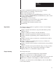
Chapter 9 Start–up and Troubleshooting Table 9.A SEARCH Functions - Industrial Terminal Key Sequence Response Positions cursor on the following program instruction. Positions cursor on preceding program instruction. Displays previous rung. Displays following rung. Search Displays first rung of program. Search Displays END statement of program. Search Display Search A xxxxxx Search B xxx Search -[ B ]- Search 8 Single rung display. (Press same key sequence to restore multiple rung display.
Chapter 9 Start–up and Troubleshooting Note that this status indication is provided in both RUN and TEST modes. In the PROGRAM LOAD (or PROG) mode, however, intensity of a displayed instruction indicates cursor position. Figure 9.2 illustrates the significance of an intensified instruction for both the industrial terminal and the PLC program panel. Figure 9.2 Meaning of Intensified CRT Display Intensified insturction indicates cursor. Editing/changes to be made at this point in the rung.
Chapter 9 Start–up and Troubleshooting FORCE ON Function The FORCE ON function, available with each of the 3 programming terminals, can be a useful troubleshooting tool. When used in conjunction with the optional test rungs of section titled “Test Rungs (Optional),” this function controls the initiation of each command programmed at a station.
Chapter 9 Start–up and Troubleshooting Figure 9.3 REMOTE/LOCAL FAULT Bit Significance Processor PLC 2/20 Local Fault Possible Sources: • Disconnected data highway cable • Power off at receiving station interface module • Unused remote staiton no.
Chapter 9 Start–up and Troubleshooting Appendix A lists each ERROR CODE and its meaning. Figure 9.4 Header Rung Local Station No. 011 G Error Code Storage Word Location 077 G CEE Timeout Preset Code 015 G 02707 L Test Rungs (Optional) For start-up and troubleshooting testing, you must have some means for control of each START bit. To execute a command during testing, you can energize the START bit for each command.
Chapter 9 Start–up and Troubleshooting Optional test rungs are shown in Figure 9.5. Within this ZCL area, the START bit is unconditionally LATCHED ON (rung 2) and UNLATCHED when the DONE bit is ON (rung 3). In rung 1, a single input image table bit is the condition for the ZCL area. Figure 9.5 Optional Test Rungs Input address for ”Force On” manipulation. (Input address which is always turned OFF by I/O scan.
Chapter 9 Start–up and Troubleshooting These rungs send the command continuously, as long as the ZCL area is enabled. As a quick check of this continuous command execution and completion, another rung can be added to the test rungs within the ZCL area. This rung examines the START bit as the input condition to a counter, as shown in Figure 9.6. Using this optional counter, you can verify that the command is being executed continuously.
Chapter 9 Start–up and Troubleshooting A ladder-diagram printout can be generated on a compatible data terminal, such as a teletype or other line printer. Forms for programmer documentation are described in chapter 10. Start-up Procedures A careful start-up procedure is essential to proper Data Highway operation. With a methodical start-up procedure, cabling connections, module set-up and support programming for module communication can be tested at each station.
Chapter 9 Start–up and Troubleshooting Overall Approach In start-up testing, it is best to limit the number of things happening at one time. By carefully limiting the scope of start-up testing to a small number of variables, the source of a problem is more readily detected. Paired Testing In the early stages of Data Highway testing, limit the size of the group of stations being tested. Initially, start-up testing is done with only 2 stations communicating at a time; all other stations are OFF.
Chapter 9 Start–up and Troubleshooting Increasing the Group Size Once paired testing has been completed, execution of each command has been verified. At this point, the size of the tested group of stations is increased and station interaction of this larger group can be monitored. For this phase of testing, the same checks outlined in sections titled “Testing the Sending Station” and “Testing the Receiving Station” can be made, but without the need to test each individual command.
Chapter 9 Start–up and Troubleshooting The ERROR CODE storage word is listed in the header rung of the communication zone of program. The significance of the ERROR CODE storage word is described in section titled “Testing the Receiving Station.” Correct the communication zone rungs as indicated by the ERROR CODE. Then repeat step 3, checking the status of the PROG indicator.
Chapter 9 Start–up and Troubleshooting Sample test rungs are shown in Figure 9.5. The following steps outline the procedures for programming these rungs for testing. With the programming terminal connected, follow these procedures: 1. Display the END (of program) statement. The key sequence that displays this part of the program is as follows: [SEARCH] [ ] 2. Turn the processor mode select switch to the PROGRAM or PROG position. 3. Enter the test rungs in the format of Figure 9.
Chapter 9 Start–up and Troubleshooting With the START bit energized, proceed to the monitoring checks of the paragraph entitled “Monitoring DONE and REMOTE/LOCAL FAULT Bits.” Once these checks have been completed, the next START/DONE bit addresses can be entered in the test rung for testing of the next command. The FORCE ON function can be removed using the programming terminal.
Chapter 9 Start–up and Troubleshooting Testing the Receiving Station The receiving station is checked with the sending station for one purpose--verification of data transfer. Although this procedure may be time-consuming, it is essential in initial start-up testing and for testing whenever a command is added at a station.
Chapter 9 Start–up and Troubleshooting REMOTE/LOCAL FAULT Indicator ON As recommended in chapter 7, some indicator must be controlled by the status of the REMOTE and LOCAL FAULT bits at each station processor. Should this indicator go ON, connect and initialize a programming terminal and follow these procedures to isolate the source of the fault condition. (The steps of this procedure are outlined in the example of Figure 9.7.) Figure 9.
Chapter 9 Start–up and Troubleshooting on the program panel or industrial terminal, observe the status indicators of the terminal carefully. Due to CRT delay time, the intensity of an EXAMINE OFF instruction, which shows its status, may not change as rapidly as does the actual ON/OFF status of the FAULT bit. (Recall that programming re-tries caused the FAULT bit to be continuously turned ON and OFF.) Thus, it may take a few seconds for the programming terminal to show a change in FAULT bit status.
Chapter 9 Start–up and Troubleshooting 4. Lift the plastic lever on the module to break its backplane connection. 5. Firmly grasp the sides of the module and pull it gently from the I/O chassis slot. Installing the Replacement Module 1. Set module switches to proper positions, then replace the switch cover. 2. Insert the replacement module in the I/O chassis. Snap down the latch on the top of the chassis and re-connect the cables to module sockets.
Chapter 9 Start–up and Troubleshooting Figure 9.8 Disconnecting a Station Trunkline Out Trunkline In 4 Cable Wiring Cable Blue Clear Shield Trunkline 1 3 Dropline 6 8 2 2 3 7 1770–SC Station Connector 1 2 3 15–Pin Connector Pin 6 Blue Pin 7 Shield Pin 8 Clear Ground Wire (Green) #12 Ga. to Earth Ground Dropline Cable Notes: To Data Highway Module 1 Twist trunkline wires of same color before securing to screw–clamp terminals 1, 2 and 3.
Chapter 9 Start–up and Troubleshooting Chapter Summary Procedures for start-up and troubleshooting were discussed in this chapter.
Chapter 9 Start–up and Troubleshooting 9-24
Chapter 10 Design Aids and Documentation General This chapter provides programmer aids to help in writing, organizing, and documenting a program for a communication adapter module. Program Summary Figure 10.1 is a sample program that incorporates both a communication zone and the support programming recommended for the single command programmed in this zone. Figure 10.
Chapter 10 Design Aids and Documentation The rungs used in this example illustrate the programming principles of chapters 5 through 7 of this manual. Of course, user application programming may vary widely from this example. In any case, certain types of support programming should be used in any program for a command at a station. Support programming for each command includes: START bit LATCH and UNLATCH control REMOTE/LOCAL FAULT bit monitoring Each of these parts of the program is shown in Figure 10.1.
Chapter 10 Design Aids and Documentation Figure 10.2 PLC-2/20 Processor Memory Organization Decimal Words Used in Each Word Area 17 16 15 14 13 12 11 10 07 06 05 04 03 02 01 00 Total Decimal Word Used 8 Processor Work Area No.
Chapter 10 Design Aids and Documentation Figure 10.3 Mini-PLC-2/15 Memory Organization Total Decimal Words Bit Address Word Address Decimal Words Per Area 000 00 007 010 17 00 017 020 17 00 026 027 030 17 Processor Work Area No. 1 8 8 Output Image Table 16 8 Bit/Word Storage 24 8 64 40 72 8 Reserved 1 2 Timer/Counter Accumulated Values (AC) (or Bit/Word Storage) 3 00 077 100 17 00 107 110 17 00 117 120 17 00 Processor Work Area No.
Chapter 10 Design Aids and Documentation Figure 10.4 PLC-2/30 Memory Organization Total Decimal Words Octal Word Address Decimal Words Per Area 000 8 8 64 56 72 8 128 56 Processor Work Area No. 1 Rack 1 010–017 Rack 2 020–027 Rack 3 Rack 4 Rack 5 030–037 040–047 050–057 Rack 6 Rack 7 060–067 070–077 007 010 1 77 100 Processor Work Area No.
Chapter 10 Design Aids and Documentation Figure 10.5 Mini-PLC-2 Memory Organization Octal Address Decimal Words Used in Each Area Total Decimal Words Used 8 8 Word 17 16 15 14 13 12 11 10 07 06 05 04 03 02 01 00 000 Processor Work Area No.
Chapter 10 Design Aids and Documentation Figure 10.6 Mini-PLC-2/05 Memory Organization Total Decimal Words Bit Address Word Address Decimal Words Per Area 000 00 007 010 17 00 017 020 17 00 026 027 030 17 077 100 17 00 Processor Work Area No. 1 8 8 Output Image Table 8 16 Bit/Word Storage 8 24 Reserved 64 40 72 8 1 2 Timer/Counter Accumulated Values (AC) (or Bit/Word Storage) 3 00 Processor Work Area No.
Chapter 10 Design Aids and Documentation Figure 10.7 Sample Form (publication 5030) for Switch Settings on Communication Adapter Module (cat. no. 1771-KA2) DATE: BY: ALLEN–BRADLEY DATA HIGHWAY SWITCH SETTINGS COMMUNICATIONS ADAPTER MODULE CAT. NO. 1771–KA (Publication 5030 –– October, 1980) STATION NO. INSTRUCTIONS: USE A PENCIL TO DARKEN SWITCHES TO SHOW PROPER SETTINGS, AS SHOWN. KEEP THIS FORM WHERE IT CAN BE EASILY REFERENCED. NO. 5 –– SEND UNPROTECTED COMMANDS w ON –– ENABLED w OFF –– DISABLED NO.
Chapter 10 Design Aids and Documentation Figure 10.8 Sample Form (publication 5032) for Command Listing--From Station DATE: BY: ALLEN–BRADLEY DATA HIGHWAY COMMAND LISTING – FROM STATION (Publication 5032 – October, 1980) STATION NO. EXAMPLE: COMMANDS AT THIS STATION START BITS COMMAND TYPE PRIORITY/ NORMAL 04010 WRITE N START BITS COMMAND TYPE PRIORITY/ NORMAL REMOTE STATION NO. ADDRESSED 022 REMOTE STATION NO.
Chapter 10 Design Aids and Documentation Figure 10.9 Sample Form (publication 5033) for Command Listing--To Station DATE: BY: ALLEN–BRADLEY DATA HIGHWAY COMMAND LISTING – TO STATION (Publication 5033 – October, 1980) STATION NO. DIRECTIONS: USE THIS FORM TO DOCUMENT COMMANDS RECEIVED AT THIS STATION FROM OTHER STATIONS. EXAMPLE: REMOTE STATION SENDING COMMAND STATION NO. 010 REMOTE STATION SENDING COMMAND STATION NO.
Chapter 10 Design Aids and Documentation We have tried to present information on the KA2 module in a way that will be most helpful to you. Obviously we don’t try to make errors and omissions, but they crop up. If you feel there’s a way we could be of greater assistance, please contact us at Allen-Bradley Industrial Computer Group, Publication Department, 747 Alpha Drive, Highland Heights, Ohio 44143. Many thanks.
Chapter 10 Design Aids and Documentation 10-12
Appendix A Error Code Listing Code 00 01, 02 03 04 05 06 07 08 09 10 11 12 13 14 15 16 17 18 19 20 21 22 23 24 26 27 28 29 STS Byte of Reply Message (in Hex) 00 Meaning No Error Processor communications problem. May be processor fault.
Appendix A Error Code Listing Code STS Byte of Reply Message (in Hex) Meaning COMMUNICATIONS ERRORS (MAY BE DISPLAYED IN CONJUNCTION WITH REMOTE/LOCAL FAULT BITS) 30 31 32 33 34 35 36 Processor memory discrepancy Controller communications problem. May be processor fault. Improper command message size Invalid command code Invalid station number Attempt to send unprotected command invalid Command execution aborted by sending station processor 37 38 50 51 52 53 54 55 Command execution aborted.
Index Symbols ”transition” bit, 7-9 **Empty**, 2-4 , 2-5 , 2-11 , 8-3 , 9-6 A Acknowledgement, message, 8-4 C Cable connections, 3-9 Cable, DH/Processor, 3-11 Cables, 2-13 Chassis, 2-9 Codes, error, A-1 Codes, timeout preset, 7-16 Commands Bit write, 4-5 Comuter, 8-5 Diagnostic, 8-6 , 8-7 Privileged, 4-2 , 8-6 Protected, 4-3 Protected/Unprotected, 4-3 Read, 4-7 Write, 4-4 Communication Adapter, Module (KA2), 1-1 Connections, Data Highway, Program Interface, 2-4 D Data Highway, 1-1 , 1-2 , 2-1 , 2-9 , 3-
Index U Upload, 8-7 , 8-8 , 9-1 Using two modules, 3-4 , 5-3 X XMTG, 2-6 , 9-2 Z Zone Control Logic (ZCL) area, 5-1 , 9-10 Zone Control Logic (ZCL) areas, 5-3 I–2