
Instruction Manual

High Resolution Thermocouple/Millivolt Input Module8
Publication
1771-5.66 – October 1998
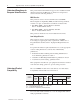
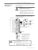
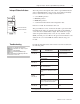
Use the following table to read data from your input module.
Dec. Bits 15 14 13 12 11 10 09 08 07 06 05 04 03 02 01 00
De o
Octal Bits 17 16 15 14 13 12 11 10 07 06 05 04 03 02 01 00
De
scripti
o
n
Word 1 Not used EE DCB HCJ LCJ RTS OR PU Diagnostics
EEPROM status bit –
(EE) calibration values could not be read.
High cold junction temperature bit - (HCJ) set when
the cold junction temperature exceeds 60.0
o
C or 140.0
o
F.
Low cold junction temperature bit - (LCJ) set when the
cold junction temperature is less than 0.0
o
C or 32.0
o
F.
Real time sample fault bit – (RTS) set when the
module updates an input buffer with new data
before the processor has read the previous data.
Monitor this bit only if you select real time sampling.
Power up bit –
(PU) set to indicate
that the module is waiting for its first
write block transfer.
Out of range bit –
(OR) set if one or
more channel inputs are above or below
the range for which you configured the
module.
Dynamic clamp bit - (DCB) Prevents rapid changes in data due
to data corruption over the opto–isolation barrier as a result of
ESD, radiation bursts, etc.
0 = feature active
1 = feature inhibited
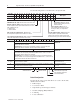
Octal Bits 17 16 15 14 13 12 11 10 07 06 05 04 03 02 01 00 Description
2 Inputs overrange Inputs underrange Inputs overrange and underrange for
c annel 1-8
Underrange bit for each channel is set to indicate an input is out of range: bit 00 for
channel 1 thru bit 07 for channel 8.
Overrange bit for each channel is set to indicate an input is out of range: bit 08 for
channel 1 thru bit 15 for channel 8. Also set for open channel detection.
c
h
annel
s
1-8
3 Inputs > high alarms Inputs < low alarms High and low alarms for
c annel 1-8
Low alarm bit for each channel is set to indicate the input is less than the low limit value
you entered in the corresponding low alarm word (BTW word 4, 6, 8, 10, 12, 14, 16, or
18): bit 00 for channel 1 thru bit 07 for channel 8.
High alarm bit for each channel is set to indicate the input has exceeded the high limit
value you entered in the corresponding high alarm word (BTW word 5, 7, 9, 11, 13, 15, 17,
or 19): bit 08 for channel 1 thru bit 15 for channel 8.
c
h
annel
s
1-8
4, 5, 6, 7, 8,
9, 10, 11
Input for channels 1-8 respectively in 0.1
o
C or 0.1
o
F resolution for temperature and 10µV
or 1
µV resolution for millivolts.
Input for channels 1-8
12 Cold junction temperature is provided in 0.1
o
C or 0.1
o
F resolution. The filter time constant
(Tau) for this value is fixed at 6.4 seconds.
Cold Junction Temperature
in _C or _F
13 Uncalibrated channel bits CF EE Not used S G O Auto-calibration word
EEPROM fault bit
Save to EEPROM bit
Offset calibration complete bit
Calibration fault bit
Gain calibration complete bit
Default Configuration
If a write block of five words with all zeroes is sent to the module,
default selections will be:
• millivolt input
• zoom center = 0mV
• temperature reported in degrees Celsius
• real time sampling (RTS) inhibited
• no filtering
• no auto-calibration