
Instruction Manual

High Resolution Thermocouple/Millivolt Input Module 5
Publication
1771-5.66 – October 1998
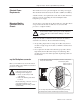
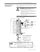
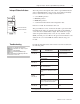
Connect your I/O devices to the field wiring arm (cat. no. 1771-WI)
shipped with the module.
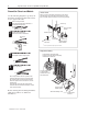
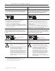
!
ATTENTION: Remove power from the 1771 I/O
chassis backplane and field wiring arm before
removing or installing an I/O module.
• Failure to remove power from the backplane or
wiring arm could cause module damage, degradation
of performance, or injury.
• Failure to remove power from the backplane could
cause injury or equipment damage due to possible
unexpected operation.
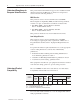
1
Short circuit
unused pins
Channel 1
Channel 2
18 Input 1 (+ lead)
17 Input 1 (– lead)
16 Input 2 (+ lead)
15 Input 2 (– lead)
14 Input 3 (+ lead)
13 Input 3 (– lead)
12 Input 4 (+ lead)
11 Input 4 (– lead)
10 Not Used
9 Not used
8 Input 5 (+ lead)
7 Input 5 (– lead)
6 Input 6 (+ lead)
5 Input 6 (– lead)
4 Input 7 (+ lead)
3 Input 7 (– lead)
2 Input 8 (+ lead)
1 Input 8 (– lead)
Terminal
Identification
Terminal Function
Field Wiring Arm
Cat. No. 1771–WI
18
17
16
1
15
14
13
12
11
10
9
8
7
6
5
4
3
2
10527–I
Connection
Diagram for the High Resolution Thermocouple/mV Input
Module (cat. no. 1771-IXHR/D)
+
–
+
–
Do not use 9 and 10 – reserved for cold junction
compensation within wiring arm.
Short circuit all unused channels by
connecting a jumper wire from the
+ terminal to the – terminal
Connect positive thermocouple leads
to even–numbered terminals, negative
leads to odd–numbered terminals.
Ground cable shield to I/O chassis
mounting bolt.
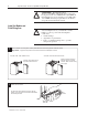
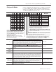
The sensor cable must be shielded. The shield must:
• extend
the length of the cable, but be connected only at the 1771 I/O chassis
•
extend up to the point of termination
Important:
The shield should extend to the termination point, exposing just enough cable to
adequately terminate the inner conductors. Use heat shrink or another suitable
insulation where the wire exits the cable jacket.
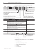
Functional
Ground
Functional
Ground
Connect Wiring to the
Field Wiring Arm