
Instruction Manual

Publication 1771-5.66 – October 1998
(Catalog Number 1771-IXHR Series C)
Use this document as a guide when installing the 1771-IXHR/C High
Resolution Thermocouple/mV input module.
To See page
Prevent Electrostatic Discharge Below
Understand Compliance to European Union Directives 2
Understand Product Compatibility 2
Calculate Power Requirements 3
Determine Module Placement 3
Key the Backplane Connector 3
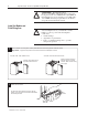
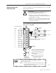
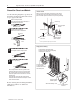
Install the Module and Field Wiring Arm 4
Connect Wiring to the Field Wiring Arm 5
Ground the Chassis and Module 6
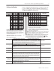
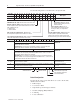
Configure the Module 7
For this reference information See page
Status Indicators 9
Troubleshooting 9
Specifications 11
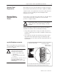
The High Resolution Thermocouple/Millivolt input module is
sensitive to electrostatic discharge.
!
ATTENTION: Electrostatic discharge can damage
integrated circuits or semiconductors if you touch
backplane connector pins. Follow these guidelines
when you handle the module:
• Touch a grounded object to discharge static potential
• Wear an approved wrist-strap grounding device
• Do not touch the backplane connector or
connector pins
• Do not touch circuit components inside the module
• If available, use a static-safe work station
• When not in use, keep the module in its
static-shield bag
This icon is used when
additional information is
available in the High Resolution
Thermocouple/Millivolt Input
Module User Manual,
publication 1771-6.5.131.
Installation Instructions
Contents
Prevent Electrostatic
Discharge