
User Manual

Troubleshooting
Chapter 8
82
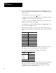
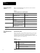
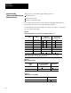
Table 8.A shows LED indications and probable causes and recommended
actions to correct common faults.
Table 8.A
Troubleshooting
Chart for the 1771-IXHR Input Module
Indication Probable Cause Recommended Action
Both LEDs are OFF No power to module
Possible short on the module
LED driver failure
Check power to I/O chassis. Cycle as necessary.
Replace module.
Red FLT LED ON and
Green RUN LED is ON
Microprocessor, oscillator or EPROM failure Replace module.
Red FLT LED ON If immediately after power-up, indicates RAM or
EPROM failure.
1
Replace module.
If during operation, indicates possible
microprocessor or backplane interface failure.
1
Replace module.
Green RUN LED is flashing Power-up diagnostics successfully completed. Normal operation.
If LED continues to flash, and write block transfers
(BTW) cannot be accomplished, you have a
possible interface failure.
Replace module.
1
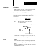
When red LED is on, the watchdog timer has timed out and backplane communications are terminated. Your user program should monitor
communication.
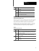
Status Reported in Word 1
Design your program to monitor status bits in the lower byte of word 1, and to
take appropriate action depending on your application requirements. You may
also want to monitor these bits while troubleshooting with your industrial
terminal. The module sets a bit (1) to indicate it has detected one or more of the
following conditions as shown in Table 8.B.
Table 8.B
Status
Reported in Word 1
Word Bit Explanation
1 00 Module is powered but has not received its first (configuration) block transfer.
The green LED is flashing.
01 One or more inputs are out of the range for which you configured the module.
02 Module updated its inputs before the processor read them. The RTS interval
timed out before the processor read the data.
03 Not used
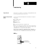
Troubleshooting with the
Indicators
Status Reported by the
Module