
User Manual

Module Calibration
Chapter 7
77
For example, if the observed value was 17, enter –53 [(0 – 17) x 3.0933 =
–53] in signed magnitude binary into the upper byte of the calibration
word for that channel. Enter 10110101 in bits 15–08 of word 20. The
lower byte will remain zero at this time.
6. Repeat steps 3 through 5 for each of the remaining input channels.
7. Initiate a write block transfer to send the corrections to the module. The
input value read by the processor should now be 0000 for all channels.
Setting Channel Gain Calibration
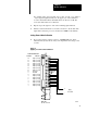
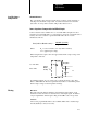
1. Now set the precision voltage source for +100.000 millivolts. Allow
sufficient time (at least 10 seconds) for the input filter and voltage source
to settle.
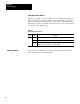
Figure 7.4
Applying
100.000mV for Gain Calibration
1
Do not
use
18 Input 1 (+ lead)
17 Input 1 (- lead)
16 Input 2 (+ lead)
15 Input 2 (- lead)
14 Input 3 (+ lead)
13 Input 3 (- lead)
12 Input 4 (+ lead)
11 Input 4 (- lead)
10 Not Used
9 Not used
8 Input 5 (+ lead)
7 Input 5 (- lead)
6 Input 6 (+ lead)
5 Input 6 (- lead)
4 Input 7 (+ lead)
3 Input 7 (- lead)
2 Input 8 (+ lead)
1 Input 8 (- lead)
Terminal
Identification
Terminal Function
Wiring Arm
Cat. No. 1771-WI
18
17
16
1
15
14
13
12
11
10
9
8
7
6
5
4
3
2
100.000mV
Apply
+
-
10533-I