
User Manual


Module Configuration
Chapter 5
56
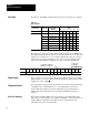
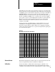
Bit/word descriptions of BTW file words 1 thru 3 (configuration), 4 thru 19
(channel alarm values), and 20 thru 27 (calibration values) are presented in
Table 5.D. Enter data into the BTW instruction after entering the instruction into
your ladder diagram program.
Table 5.D
Bit/Word
Definitions for the High Resolution Thermocouple/Millivolt Input
Module
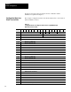
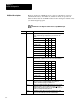
Word Bits Description
Word 1 bits 00-02 Input type codes for inputs 1 thru 8 (or 1 thru 4 if bit 06 is set to 1).
Tells the module what type of input device you connected to the
module.
Type 02 01 00
Millivolt input 0 0 0
"B" thermocouple 1 1 1
"E" thermocouple 0 0 1
"J" thermocouple 0 1 0
"K" thermocouple 0 1 1
"R" thermocouple 1 0 1
"S" thermocouple 1 1 0
"T" thermocouple 1 0 0
bits 03-05 Input type codes for inputs 5 thru 8 (bit 06 must be set to 1). Tells the
module what type of input device you connected to inputs 5 thru 8.
Type 05 04 03
Millivolt input 0 0 0
"B" thermocouple 1 1 1
"E" thermocouple 0 0 1
"J" thermocouple 0 1 0
"K" thermocouple 0 1 1
"R" thermocouple 1 0 1
"S" thermocouple 1 1 0
"T" thermocouple 1 0 0
bit 06 When set to 0 bits 00-02 define input type for all channels.
When set to 1 bits 00-02 defines input type for channels 1-4,
and bit 03-05 defines input type for channels 5-8.
bit 07 Enables X10 magnification when millivolt inputs have been selected.
Enabling this feature causes the BTR data to display +30.000mV
around the value selected by word 2. Use the digital filter (word 3) to
stabilize the readings when using this mode.
bit 08 Temperature scale bit, when set, reports temperature in
o
F; when
reset, in
o
C. The module ignores this bit for millivolt inputs.
Bit/Word Descriptions