
User Manual


Module Configuration
Chapter 5
54
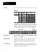
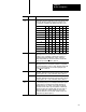
through 8 respectively. Word 28 activates the auto–calibration feature.
Calibration is explained in chapter 7.
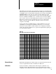
The complete configuration block for the block transfer write to the module is
defined in Table 5.C below.
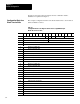
Table 5.C
Configuration
Block for the High Resolution Thermocouple/Millivolt Input
Module Block T
ransfer W
rite
Word 15 14 13 12 11 10 09 08 07 06 05 04 03 02 01 00
1 Sample Time T Z E Type Type
2 Zoom Value for Group 2 (Channels 5-8) Zoom Value for Group 1 (Channels 1-4)
3 Filter Value for Group 2 (Channels 5-8) Filter Value for Group 1 (Channels 1-4)
4 Channel 1 Low Alarm Value
5 Channel 1 High Alarm Value
6 Channel 2 Low Alarm Value
7 Channel 2 High Alarm Value
8 Channel 3 Low Alarm Value
9 Channel 3 High Alarm Value
10 Channel 4 Low Alarm Value
11 Channel 4 High Alarm Value
12 Channel 5 Low Alarm Value
13 Channel 5 High Alarm Value
14 Channel 6 Low Alarm Value
15 Channel 6 High Alarm Value
16 Channel 7 Low Alarm Value
17 Channel 7 High Alarm Value
18 Channel 8 Low Alarm Value
19 Channel 8 High Alarm Value
20 Calibration Values for Channel 1
21 Calibration Values for Channel 2
22 Calibration Values for Channel 3
23 Calibration Values for Channel 4
24 Calibration Values for Channel 5
25 Calibration Values for Channel 6
26 Calibration Values for Channel 7
27 Calibration Values for Channel 8
28 Auto-calibration Request Word
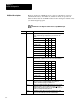
Configuration
Block for a
Block T
ransfer W
rite