
User Manual

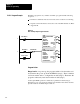

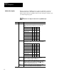

Set these bits
for input type.
Set this bit for 2 different
input types (see table 5.D)
Module Configuration
Chapter 5
52
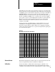
The thermocouple/millivolt input module accepts the following types of inputs:
Table 5.A
Types
of Inputs
Input
T
ype Input Type
Temperature
Range
o
C
Bits
05 04 03 02 01 00
Millivolt Millivolt -100 to +100 0 0 0 0 0 0
Thermocouple B 320 to 1800 1 1 1 1 1 1
E -270 to 1000 0 0 1 0 0 1
J -210 to 1200 0 1 0 0 1 0
K -270 to 1380 0 1 1 0 1 1
R -50 to 1770 1 0 1 1 0 1
S -50 to 1770 1 1 0 1 1 0
T -270 to 400 1 0 0 1 0 0
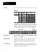
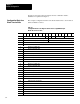
The input type is selected by setting bits in the block transfer write (BTW) file.
Two different inputs can be selected. You can have 4 inputs set for one type, and
4 inputs set for another type; or you can have all inputs the same. If you select
different types of inputs, set bit 06 to 1. If you do not select 2 different input
types, the module defaults to all inputs set to those selected by bits 00 –02.
Word 15 14 13 12 11 10 09 08 07 06 05 04 03 02 01 00
1 Sample Time T Z E Input Type Input Type
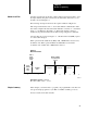
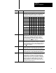
The zoom feature (word 2) can be enabled when millivolt inputs are used. This
feature allows you to view +
30mV (in 1µV increments) around a selected value
ranging from –70 to +70mV.
The temperature scale reported by the module is selected by setting bit 08 in the
configuration word. When bit 08 is set (1), the temperature is reported in
degrees Fahrenheit. When reset (0), the temperature is reported in degrees
Celsius. The temperature bit 08 is ignored when the millivolt input type is
selected.
The real time sampling (RTS) mode of operation provides data from a fixed
time period for use by the processor. RTS is invaluable for time based functions
(such as PID and totalization) in the PLC. It allows accurate time based
calculations in local or remote I/O racks.
Input
T
ype
Zoom Feature
T
emperature Scale
Real
T
ime Sampling