High Resolution Thermocouple/Millivolt Input Module Cat. No.
Important User Information Because of the variety of uses for this product and because of the differences between solid state products and electromechanical products, those responsible for applying and using this product must satisfy themselves as to the acceptability of each application and use of this product. For more information, refer to publication SGI–1.1 (Safety Guidelines For The Application, Installation and Maintenance of Solid State Control).
Table of Contents Important User Information . . . . . . . . . . . . . . . . . . . . . . . . 1 Using This Manual . . . . . . . . . . . . . . . . . . . . . . . . . . . . . . . 1 1 Purpose of Manual . . . . . . . . . . . . . . . . . . . . . . . . . . . . . . . . . . . Audience . . . . . . . . . . . . . . . . . . . . . . . . . . . . . . . . . . . . . . . . . . Vocabulary . . . . . . . . . . . . . . . . . . . . . . . . . . . . . . . . . . . . . . . . Manual Organization . . . . . . . . . . . . . . . . . .
ii Table of Contents Module Programming . . . . . . . . . . . . . . . . . . . . . . . . . . . . 4 1 Chapter Objectives . . . . . . . . . . . . . . . . . . . . . . . . . . . . . . . . . . . Block Transfer Programming . . . . . . . . . . . . . . . . . . . . . . . . . . . . PLC-2 Applications . . . . . . . . . . . . . . . . . . . . . . . . . . . . . . . . . . PLC-3 Program Example . . . . . . . . . . . . . . . . . . . . . . . . . . . . . . PLC-5 Program Example . . . . . . . . . . . . . . . . . . . . . . .
Table of Contents iii Troubleshooting . . . . . . . . . . . . . . . . . . . . . . . . . . . . . . . . 8 1 Chapter Objective . . . . . . . . . . . . . . . . . . . . . . . . . . . . . . . . . . . Diagnostics Reported by the Module . . . . . . . . . . . . . . . . . . . . . . Troubleshooting with the Indicators . . . . . . . . . . . . . . . . . . . . . . . Status Reported by the Module . . . . . . . . . . . . . . . . . . . . . . . . . . Chapter Summary . . . . . . . . . . . . . . . . . . . . . . . . . . . .
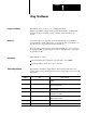
Chapter Using This Manual Purpose of Manual This manual shows you how to use your High Resolution Thermocouple/Millivolt input module with an Allen–Bradley programmable controller. It helps you install, program, calibrate, and troubleshoot your module. Audience You must be able to program and operate an Allen–Bradley programmable controller (PLC) to make efficient use of your input module. In particular, you must know how to program block transfer instructions.
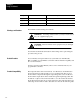
Chapter 1 Using This Manual Chapter Title Appendix A Specifications Appendix B Programming Examples Appendix C Thermocouple Characteristics Warnings and Cautions Topics Covered Your module's specifications Extractions from NBS Monograph 125 (IPTS-68) This manual contains warnings and cautions. WARNING: A warning indicates where you may be injured if you use your equipment improperly. CAUTION: Cautions indicate where equipment may be damaged from misuse.
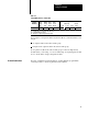
Chapter 1 Using This Manual Table 1.A Compatibility and Use of Data Table Catalog Number 1771-IXHR Input Image Bits 8 Use of Data Table Output Read Image Block Bits Words 8 12/13 Write Block Words 27/28 Compatibility 1/2 -slot Yes Addressing Chassis 1-slot 2-slot Series Yes Yes A and B A = Compatible with 1771-A1, A2, A4 chassis. B = Compatible with 1771-A1B, A2B, A3B, A4B chassis.
Chapter Chapter 2 2 Overview of the High Resolution Thermocouple/Millivolt Input Module Chapter Objectives This chapter gives you information on: features of the input module how an input module communicates with programmable controllers Module Description The High Resolution Thermocouple/Millivolt input module is an intelligent block transfer module that interfaces analog input signals with any Allen–Bradley programmable controllers that have block transfer capability.
Chapter 2 Overview of the High Resolution Thermocouple/Millivolt Input Module self–diagnostics and status reporting at power–up detection of open circuit if thermocouple fails automatic offset and gain calibration for each channel software calibration of all channels, eliminating potentiometers programmable filters for each group of 4 inputs X10 magnification (zoom) for millivolt mode How Analog Modules Communicate with Programmable Controllers The processor transfers data to and from the module using BT
Chapter 2 Overview of the High Resolution Thermocouple/Millivolt Input Module 4. When instructed by your ladder program, the processor performs a read block transfer of the values and stores them in a data table. 5. The processor and module determine that the transfer was made without error, and that input values are within specified range. 6. Your ladder program can use and/or move the data (if valid) before it is written over by the transfer of new data in a subsequent transfer. 7.
Chapter 3 Installing the High Resolution Thermocouple/Millivolt Input Module Chapter Objectives This chapter gives you information on: calculating the chassis power requirement choosing the module’s location in the I/O chassis keying a chassis slot for your module wiring the input module’s field wiring arm installing the input module Before You Install Your Input Module Before installing your input module in the I/O chassis you must: Action required: Electrostatic Damage Refer to: Calculate the pow
Chapter 3 Installing the High Resolution Thermocouple/Millivolt Input Module Add this value to the requirements of all other modules in the I/O chassis to prevent overloading the chassis backplane and/or backplane power supply. Module Location in the I/O Chassis Place your module in any slot of the I/O chassis except for the extreme left slot. This slot is reserved for processors or adapter modules. Group your modules to minimize adverse affects from radiated electrical noise and heat.
Chapter 3 Installing the High Resolution Thermocouple/Millivolt Input Module Keying Bands 2 4 6 8 10 12 14 16 18 20 22 24 26 28 30 32 34 36 Upper Connector 14288 CAUTION: The High Resolution Thermocouple/Millivolt Input Module uses the same keying slots as the 1771–IXE Thermocouple/Millivolt Input Module. If you are replacing a 1771–IXE with a 1771–IXHR, the ladder program must be modified to accept the new block transfer format.
Chapter 3 Installing the High Resolution Thermocouple/Millivolt Input Module Figure 3.
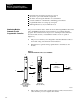
Chapter 3 Installing the High Resolution Thermocouple/Millivolt Input Module Figure 3.3 Cable Grounding Ground Shield at I/O chassis mounting bolt Shield and drain twisted into single strand Field Wiring Arm 17798 Refer to Wiring and Grounding Guidelines, publication 1770-4.1 for additional information.
Chapter 3 Installing the High Resolution Thermocouple/Millivolt Input Module Installing the Input Module When installing your module in an I/O chassis: 1. First, turn off power to the I/O chassis: WARNING: Remove power from the 1771 I/O chassis backplane and wiring arm before removing or installing an I/O module. Failure to remove power from the backplane could cause injury or equipment damage due to possible unexpected operation.
Chapter 3 Installing the High Resolution Thermocouple/Millivolt Input Module Chapter Summary In this chapter you learned how to install your input module in an existing programmable controller system and how to wire to the field wiring arm.
Chapter Module Programming Chapter Objectives In this chapter, we describe Block Transfer programming Sample programs in the PLC–3 and PLC–5 processors Module scan time issues Block Transfer Programming Your module communicates with the processor through bidirectional block transfers. This is the sequential operation of both read and write block transfer instructions.
Chapter 4 Module Programming PLC-3 Program Example Block transfer instructions with the PLC–3 processor use one binary file in a data table section for module location and other related data. This is the block transfer control file. The block transfer data file stores data that you want transferred to the module (when programming a block transfer write) or from the module (when programming a block transfer read). The address of the block transfer data files are stored in the block transfer control file.
Chapter 4 Module Programming After this single block transfer write is performed, the module returns to continuous block transfer reads automatically.
Chapter 4 Module Programming PLC-5 Program Example The PLC–5 program is very similar to the PLC–3 program with the following exceptions: You must use enable bits instead of done bits as the conditions on each rung. A separate control file must be selected for each of the BT instructions. Refer to Appendix B. Figure 4.
Chapter 4 Module Programming Module Scan Time Scan time is defined as the amount of time it takes for the input module to read the input channels and place new data into the data buffer. Scan time for your module is shown in Figure 4.3. The following description references the sequence numbers in Figure 4.3.
Chapter Module Configuration Chapter Objectives In this chapter you will read how to configure your module’s hardware, condition your inputs and enter your data. Configuring the Module Because of the many analog devices available and the wide variety of possible configurations, you must configure your module to conform to the analog device and specific application that you have chosen.
Chapter 5 Module Configuration Input Type The thermocouple/millivolt input module accepts the following types of inputs: Table 5.
Chapter 5 Module Configuration In the RTS mode the module scans and updates its inputs at a user defined time interval ( ∆T) instead of the default interval. The module ignores block transfer read (BTR) requests for data until the sample time period elapses. The BTR of a particular data set occurs only once at the end of the sample period and subsequent requests for transferred data are ignored by the module until a new data set is available.
Chapter 5 Module Configuration through 8 respectively. Word 28 activates the auto–calibration feature. Calibration is explained in chapter 7. Configuration Block for a Block Transfer Write The complete configuration block for the block transfer write to the module is defined in Table 5.C below. Table 5.
Chapter 5 Module Configuration E = enable bit for input types (refer to bit/word description) T = temperature scale bit (refer to bit/word description) Z = zoom enable: 0 = normal 10µV; 1 = X10 (1µV) 5 5
Chapter 5 Module Configuration Bit/Word Descriptions Bit/word descriptions of BTW file words 1 thru 3 (configuration), 4 thru 19 (channel alarm values), and 20 thru 27 (calibration values) are presented in Table 5.D. Enter data into the BTW instruction after entering the instruction into your ladder diagram program. Table 5.
Chapter 5 Module Configuration Word Word 1 (cont.) Bits bits 09-15 Description Real time sample interval bits determine the sample time for updating module inputs. You select sample time in 0.025 second intervals using binary code. (All values between 0.025 and 3.1 seconds in 0.025 second intervals are available.) We tabulated some values for you. Sample Time Word 2 Word 3 Words 4 thru 19 15 14 13 12 11 10 09 0.1 0 0 0 0 1 0 0 0.5 0 0 1 0 1 0 0 0.6 0 0 1 1 0 0 0 0.
Chapter 5 Module Configuration Word Bits Description Words 20 thru 27 Calibration words are a composite of two independent bytes for each channel. Enter calibration data in signed magnitude binary only. The most significant bit in each byte is the sign bit; set for negative, reset for positive. Use the high byte (bits 08-15) for offset correction, the low byte (bits 00-07) for gain correction for each channel. Use word 20 for channel 1 thru word 27 for channel 8.
Chapter 6 Module Status and Input Data Chapter Objectives In this chapter you will read about: reading data from your module input module read block format Reading Data from the Module Block transfer read programming moves status and data from the input module to the processor’s data table in one I/O scan (Table 6.A). The processor user program initiates the request to transfer data from the input module to the processor.
Chapter 6 Module Status and Input Data Bit/Word Descriptions The complete bit/word description for the block transfer read from the module is defined in Table 6.B. Table 6.
Chapter 6 Module Status and Input Data Word Bit Word 13 Chapter Summary Definition Auto-calibration word. Bit 00 Offset calibration complete bit Bit 01 Gain calibration complete bit Bit 02 Save to EEPROM bit Bits 03-05 Not used Bit 06 EEPROM fault bit Bit 07 Calibration fault bit Bits 08-15 Uncalibrated channel bits In this chapter you learned the meaning of the status information that the input module sends to the processor.
Chapter Module Calibration Chapter Objective In this chapter we tell you how to calibrate your module. Tools and Equipment To calibrate your module you will need the following tools and equipment: Tool or Equipment Description Model/Type Precision Voltage Source 0-100mV, 1µV resolution Analogic 3100, Data Precision 8200 or equivalent Industrial Terminal and Interconnect Cable Programming terminal for A-B family processors Cat. No. 1770-T3 or Cat. No. 1784-T45, -T47, -T50, etc.
Chapter 7 Module Calibration Performing Auto-calibration Calibration of the module consists of applying 0.000mV across each input channel for offset calibration, and +100.000mV across each input channel for gain correction. Offset Calibration Normally all inputs are calibrated together. To calibrate the offset of an input, proceed as follows: 1. Apply power to the module. 2. Connect shorting links, or apply 0.000mV across each input channel on the 1771–WI field wiring arm as shown in Figure 7.1.
Chapter 7 Module Calibration Table 7.A Write Block Transfer Word 28 Word/Bit 15 14 13 12 11 10 09 08 07 06 05 04 Inhibit Calibration on Channel Word 28 8 7 6 5 4 3 2 03 02 01 00 Requested Auto-Calibration 1 Set these bits to 0 Requested Requested Requested Save clamp Gain Cal. Values inhibit Requested Offset Cal. NOTE: Normally, all channels are calibrated simultaneously (bits 08–15 of word 28 are octal 0).
Chapter 7 Module Calibration Figure 7.2 Applying 100.
Chapter 7 Module Calibration Save Calibration Values If any ”uncalibrated channel” bits (bits 08–15 of BTR word 13) are set, a save cannot occur. Auto–calibration should be performed again, starting with offset calibration. If the module has a faulty channel, the remaining functioning channels can be calibrated by inhibiting calibration on the faulty channel. The module can be run with the new calibration values, but will lose them on power down.
Chapter 7 Module Calibration Figure 7.3 Shorting Inputs for Offset Calibration Terminal Identification Function Shorting link. Repeat for each channel 1 Do not use Short each input, or apply 0.000mV across each input channel.
Chapter 7 Module Calibration For example, if the observed value was 17, enter –53 [(0 – 17) x 3.0933 = –53] in signed magnitude binary into the upper byte of the calibration word for that channel. Enter 10110101 in bits 15–08 of word 20. The lower byte will remain zero at this time. 6. Repeat steps 3 through 5 for each of the remaining input channels. 7. Initiate a write block transfer to send the corrections to the module. The input value read by the processor should now be 0000 for all channels.
Chapter 7 Module Calibration 2. Record the input value read by the processor in the BTR file (word 4 for channel 1). Determine the percentage difference from 10000 and the sign of the correction. You can adjust the correction up to +0.19379%. A negative correction means that the reading was too high and you want to subtract a corrective amount from that reading. A positive correction means that the reading was too low and you want to add a corrective amount to that reading.
Chapter 7 Module Calibration 4. Repeat the above steps 2 and 3 for channels 2 through 8. 5. Initiate a write block transfer to send the corrections to the module. The input value read by the processor should now be 10000 for all channels. 6. If the correction changes the result in the wrong direction, change the sign and reenter it. Important: If the % correction required is larger than +0.19379, check your reference voltage. If the reference voltage is correct, perform auto–calibration.
Chapter 8 Troubleshooting Chapter Objective We describe how to troubleshoot your module by observing LED indicators and by monitoring status bits reported to the processor.
Chapter 8 Troubleshooting Troubleshooting with the Indicators Table 8.A shows LED indications and probable causes and recommended actions to correct common faults. Table 8.A Troubleshooting Chart for the 1771-IXHR Input Module Indication Probable Cause Recommended Action Both LEDs are OFF No power to module Possible short on the module LED driver failure Check power to I/O chassis. Cycle as necessary. Replace module.
Chapter 8 Troubleshooting Word Bit Word 1 (cont) 04 The module's ambient temperature is below 0oC. Temperature readings will be inaccurate. 05 The module's ambient temperature is above 60oC. Temperature readings will be inaccurate. 06 Not used 07 EEPROM calibration constants could not be read. The module will continue to operate but readings may be inaccurate.
Chapter 8 Troubleshooting Status Reported in Word 13 Design your program to monitor status bits in word 13 during auto–calibration, and to take appropriate action depending on your requirements. You may also want to monitor these bits while troubleshooting with your industrial terminal. The module sets a bit (1) to indicate it has detected one or more of the following conditions as shown in Table 8.D. Table 8.D Status Reported in Word 13 Word Bit 13 6 The EEPROM could not be written.
Appendix A Specifications Number of Inputs 8, all of the same type or 4 each of 2 different types I/O Chassis Location Any single I/O module slot Type of Input (Selectable) Type B, Pt-30% Rh/Pt-6% Rh Type E, chromel/constantan Type J, iron/constantan Type K, chromel/alumel Type R, Pt/Pt-13% Rh Type S, Pt/Pt-10% Rh Type T, copper/constantan Millivolt Thermocouple Linearization IPTS-68 standard, NBS MN-125 Cold Junction Compensation Range: 0 to 60oC Accuracy: +0.
Appendix A Specifications The accuracy of your thermocouple readings depends on: High Resolution Thermocouple/Millivolt Input module accuracy Module Accuracy lead resistance effect accuracy of the thermocouple The accuracy of the module is shown in Table A.A and Table A.B at ambient temperature (25oC) and over the temperature range (0–60oC). Use the calibration procedure in Chapter 7 to adjust your module to compensate for your specific environment. Table A.
Appendix A Specifications Lead Resistance Compensation Allowable Distances The open thermocouple detection circuit injects a current of approximately 7.3 nanoamps into the thermocouple cable. A total lead resistance of 1370 ohms (685 ohms one–way) cable resistance will produce 10uV of error. Source Impedance Compensation for Millivolt Inputs Source resistance causes similar errors to occur with millivolt inputs.
Appendix Programming Examples Sample Programs for the Input Module The following are sample programs for entering data in the configuration words of the write block transfer instruction when using the PLC–3 or PLC–5 family processors. PLC-3 Family Processors Following is a sample procedure for entering data in the configuration words of the write block transfer instruction when using a PLC–3 processor. For a complete sample program, refer to Figure 4.2.
Appendix B Programming Examples 4. When you have entered your data, press [ENTER]. If you make a mistake, make sure the cursor is over the word you desire to change. Enter the correct data and press [ENTER]. Figure B.
Appendix B Programming Examples Figure B.
Appendix C Thermocouple Restrictions (Extracted from NBS Monograph 125 (IPTS-68)) General Following are some restrictions extracted from NBS Monograph 125 (IPTS–68) issued March 1974 on thermocouples B, E, J, K, R, S and T: B (Platinum - 30% Rhodium vs Platinum - 6% Rhodium) Type Thermocouples “The ASTM manual STP 470 [1970] indicates the following restrictions on the use of B type thermocouples at high temperatures: They should not be used in reducing atmospheres, nor in those containing metallic or n
Appendix C Thermocouple Restrictions The negative thermoelement is subject to deterioration above about 871C, but the thermocouple may be used up to 1000C for short periods.” “The ASTM Manual [1970] indicates the following restrictions .. at high temperatures. They should not be used in sulfurous, reducing or alternately reducing and oxidizing atmospheres unless suitably protected with protecting tubes.
Appendix C Thermocouple Restrictions “Commercial iron undergoes a magnetic transformation near 769C and crystal transformation near 910C. Both of these transformations, especially the latter, seriously affect the thermoelectric properties of iron, and therefore, the Type J thermocouples. ... If Type J thermocouples are taken to high temperatures, especially above 900C, they will lose accuracy of their calibration when they are recycled to lower temperatures.
Appendix C Thermocouple Restrictions alters the calibration. They should also not be used in atmospheres that promote ”green–rot” corrosion (those with low, but not negligible, oxygen content).” “ASTM Standard E230–72 in the Annual Book of ASTM Standards [1972] specifies that the standard limits of error for Type K commercial thermocouples be +/–2.2C between 0 and 277C and +/–3/4 percent between 277 and 1260C. Limits of error are not specified for the Type K thermocouples below 0C.
Appendix C Thermocouple Restrictions T thermocouples are less suitable for use in the subzero range than Type E thermocouples.” “Type T thermocouples are recommended by the ASTM [1970] for use in the temperature range from –184 to 371C in vacuum or in oxidizing, reducing or inert atmospheres. The recommended upper temperature limit for continuous service of protected Type T thermocouples is set at 371C for AWG 14 (1.6mm) thermoelements, since Type TP thermoelements oxidize rapidly above this temperature.
Index A Accuracy, 2 3 B K Keying your module, 3 2 M Bit/Word descriptions, 1771-IXE, 5 6 Module installation, 3 6 Block transfer programming, 4 1 Module location, 3 2 Block transfer read, 6 1 bit/word descriptions, 1771-IXE, 6 2 BTR word assignments, 1771-IXE, 6 1 P Power requirements, 3 1 C Calibration channel offset, 1771-IXE, 7 5 procedure for 1771-IXE, 7 5 tools, 7 1 Communication, how data is transferred, 2 2 Compatibility, use of data table, 1 3 Configuring your module 1771-IXE features, 5
With offices in major cities worldwide WORLD HEADQUARTERS Allen-Bradley 1201 South Second Street Milwaukee, WI 53204 USA Tel: (414) 382-2000 Telex: 43 11 016 FAX: (414) 382-4444 EUROPE/MIDDLE EAST/AFRICA HEADQUARTERS Allen-Bradley Europa B.V. Amsterdamseweg 15 1422 AC Uithoorn The Netherlands Tel: (31) 2975/60611 Telex: (844) 18042 FAX: (31) 2975/60222 Publication 1771–6.5.