
Installation Instructions Owner's manual
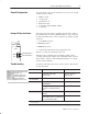

Thermocouple/Millivolt Input Module6
6#-*$"5*0/ ; $50#&3
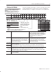
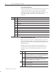
Recommended maximum cable length for voltage-mode input
devices is 50 feet, due to possible signal degradation and electrical
noise immunity in typical industrial environments.
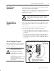
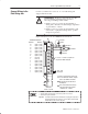
When using shielded cable or shielded thermocouple extension wire,
ground the foil shield and drain wire only at one end of the cable. We
recommend that you wrap the foil shield and drain wire together, and
connect them to a chassis mounting bolt, grounding stud or chassis
single-point grounding point. Use heat shrink tubing to seal the exit
point of the wires. At the opposite end of the cable, tape exposed
shield and drain wire with electrical tape to insulate it from electrical
contact.
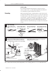
&.07& " -&/(5) 0' $"#-&
+"$,&5 '30. 5)& 5)&3.0$061-&
$"#-&
6-- 5)& '0*- 4)*&-% "/% #"3&
%3"*/ 8*3& '30. 5)& */46-"5&%
8*3&4
"3& %3"*/
8*3&
/46-"5&%
8*3&4
0*-
4)*&-%
8*45 5)& '0*- 4)*&-% "/% %3"*/
8*3& 50(&5)&3 50 '03. " 4*/(-&
453"/%
55"$) " (306/% -6( "/% "11-:
)&"5 4)3*/, 56#*/( 50 5)& &9*5 "3&"
&-%&/ "#-&
&/(5) "4 /&&%&%
306/%*/( 56%
4& 5)& $61 8"4)&3 *' $3*.1;0/ -6(4 "3& /05 64&%
306/% 6(
306/% 6(
5"3
!"4)&3
)"44*4
*%& -"5&
65 "/% "15*7&
!"4)&3
95&3/"-;5005) !"4)&34
)3&"%;'03.*/( 4$3&8
)*&-% "/% 3"*/
58*45&% 50(&5)&3
)*&-% "/% 3"*/
58*45&% 50(&5)&3
95&/% 4)*&-% 50 5&3.*/"5*0/ 10*/5 9104& +645 &/06() $"#-& 50
"%&26"5&-: 5&3.*/"5& *//&3 $0/%6$5034
4& )&"5 4)3*/, 56#*/( 03
05)&3 46*5"#-& */46-"5*0/
8)&3& 8*3& &9*54 $"#-& +"$,&5
65
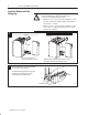
!)&/ :06 $0//&$5 (306/%*/( $0/%6$5034 50 5)& $)"44*4
(306/%*/( 456% 1-"$& " 45"3 8"4)&3 6/%&3 5)& '*345 -6( 5)&/
1-"$& " /65 8*5) $"15*7& -0$, 8"4)&3 0/ 501 0' &"$) (306/% -6(
&'&3 50 /%6453*"- 650."5*0/ !*3*/( "/% 306/%*/( 6*%&-*/&4 '03 0*4& ..6/*5: 16#-*$"5*0/ ; '03 "%%*5*0/"- */'03."5*0/