
Installation Instructions Owner's manual
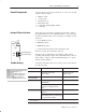

Thermocouple/Millivolt Input Module 5
5",)#!4)/. : #4/"%2
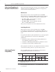
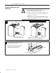
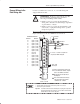
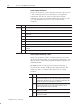
Connect your I/O devices to the cat. no. 1771-WI wiring arm
shipped with the module.
!
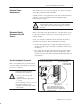
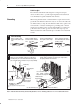
ATTENTION: Remove power from the 1771 I/O
chassis backplane and field wiring arm before
removing or installing an I/O module.
• Failure to remove power from the backplane or
wiring arm could cause module damage, degradation
of performance, or injury.
• Failure to remove power from the backplane could
cause injury or equipment damage due to possible
unexpected operation.
Input connections for the 1771-IXE/D are shown below.
+
+
–
–
1
/ ./4 53% 2%3%26%$ &/2 #/,$ *5.#4)/.
#/-0%.3!4)/. 7)4(). 7)2).' !2-
(/24 #)2#5)4
5.53%$ 0).3
(!..%,
(!..%,
.054 ,%!$
.054 ,%!$
.054 ,%!$
.054 ,%!$
.054 ,%!$
.054 ,%!$
.054 ,%!$
.054 ,%!$
/4 3%$
/4 53%$
.054 ,%!$
.054 ,%!$
.054 ,%!$
.054 ,%!$
.054 ,%!$
.054 ,%!$
.054 ,%!$
.054 ,%!$
%2-).!, $%.4)&)#!4)/.
%2-).!, 5.#4)/.
)2).' 2-
!4 /
/..%#4 0/3)4)6% 4(%2-/#/50,% ,%!$3
4/ %6%..5-"%2%$ 4%2-).!,3 .%'!4)6%
,%!$3 4/ /$$.5-"%2%$ 4%2-).!,3
2/5.$ #!",% 3()%,$ 4/ #(!33)3
-/5.4).' "/,4
(% 3%.3/2 #!",% -534 "% 3()%,$%$ (% 3()%,$ -534
• %84%.$ 4(% ,%.'4( /& 4(% #!",% "54 "% #/..%#4%$ /.,9 !4 4(% #(!33)3
• %84%.$ 50 4/ 4(% 0/).4 /& 4%2-).!4)/.
(% 3()%,$ 3(/5,$ %84%.$ 4/ 4(% 4%2-).!4)/. 0/).4 %80/3).' *534 %./5'( #!",% 4/
!$%15!4%,9 4%2-).!4% 4(% )..%2 #/.$5#4/23 3% (%!4 3(2).+ /2 !./4(%2 35)4!",%
).35,!4)/. 7(%2% 4(% 7)2% %8)43 4(% #!",% *!#+%4
5.#4)/.!,
2/5.$
5.#4)/.!,
2/5.$
(/24 #)2#5)4 !,, 5.53%$ #(!..%,3 "9
#/..%#4).' ! *5-0%2 7)2% &2/- 4(%
4%2-).!, 4/ 4(% 4%2-).!,