
User Manual


Programming Examples B–3
+$'&%#*&)( - #,
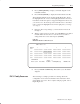
1. Press [SHIFT][MODE] to display your ladder diagram on the
industrial terminal.
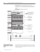
2. Press DD,03:0[ENTER] to display the block transfer write file.
The industrial terminal screen should look like Figure B.2. Notice
the highlighted block of zeroes. This highlighted block is the cursor.
It should be in the same place as it appears in Figure B.2. If it is not,
you can move it to the desired position with the cursor control keys.
Once you have the highlighted cursor in the right place, you can go
on to step 3.
3. Enter the data corresponding to your bit selection in words 0
through 4.
4. When you have entered your data, press [ENTER]. If you make a
mistake, make sure the cursor is over the word you desire to
change. Enter the correct data and press [ENTER].
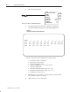
Figure B.2
Write Block Transfer for a PLC-3 Processor
!"
! "
5. Press [CANCEL COMMAND]. This returns you to the ladder
diagram.
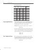
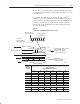
The following is a sample procedure for entering data in the
configuration words of the block transfer write instruction when
using a PLC–5 processor. For a complete sample program, refer to
Figure Figure 3.3.
PLC-5 Family Processors