
User Manual


Programming ExamplesB–2
1'+*(&0*-, 4 &3
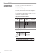
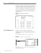
Use the above procedure to enter the required words of the write
block transfer instruction. Be aware that the block length will depend
on the number of channels selected and whether alarming or user
calibration are implemented. For example, the block may contain
only 1 word if no alarming or user calibration are implemented, but
may contain 27 words if using 8 inputs with alarming and user
calibration. The PLC–2 family write block transfer data file should
look like Figure B.1.
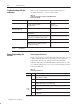
Figure B.1
Write Block Transfer Data Transfer for a PLC-2 Family
Processor
! !
! % ! ! !
$ #!
"
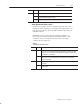
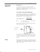
Following is a sample procedure for entering data in the
configuration words of the write block transfer instruction when
using a PLC–3 processor. For a complete sample program, refer to
Figure Figure 3.2.
To enter data in the configuration words, follow these steps:
Example:
Enter the following rung for a write block transfer:
!#
"
"
!
!
!
$ #!
!
!
!
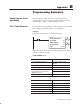
-2)/".*0
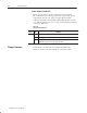
F0003:0000 is the address of the write block transfer data file. You
want to enter/examine word 1.
PLC-3 Family Processors