
User Manual

Specifications A–3
)"!(!%$ + *
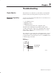
Allowable Distances
The open thermocouple detection circuit injects a current of
approximately 7.3 nanoamps into the thermocouple cable. A total
lead resistance of 1370 ohms (685 ohms one–way) cable resistance
will produce +1 count (10uV) of error.
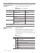
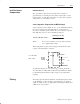
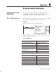
Source Impedance Compensation for Millivolt Inputs
Source resistance causes similar errors to occur with millivolt inputs.
If source resistance is less than 100 ohms, no compensation is
necessary to maintain stated accuracy. If source resistance is greater
than 100 ohms, the error can be calculated as follows:
&&%& !$ "!&(!%$ %)$('
'
!$
'
% #'
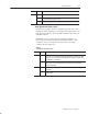
Where R
s
= source resistance (one–way cable resistance)
V
in
= applied input voltage
When using thermocouples, Vin is the approximate thermocouple
voltage of the temperature of interest.
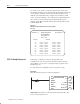
!$
#% #'
%
&&%&
$(&$"
%)"
!&)!(&*
To maintain a display error of < 5uV at V
in
= OV, R
S
should be <
341 ohms. Refer to NBS NM–125 Thermocouple Reference Tables
for determining actual thermocouple voltage versus temperature
readings.
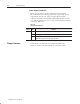
The analog input module has hardware–based high frequency filters
on all channels to reduce the effect of electrical noise on the input
signal. In addition, a 6–pole digital filter, which begins rolling off at
8.0Hz, is also incorporated.
Lead Resistance
Compensation
Filtering