
User Manual


6–9Module Calibration
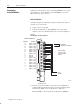
4. Repeat the above steps 2 and 3 for channels 2 through 8.
5. Initiate a write block transfer to send the corrections to the
module. The input value read by the processor should now be
10000 (A000 for BCD) for all channels.
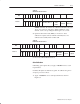
6. If the correction changes the result in the wrong direction, change
the sign and reenter it.
Important: If the % correction required is larger than
+0.19379, check your reference voltage. If the
reference voltage is correct, perform
auto–calibration.
In this chapter, you learned how to calibrate your input module.
Chapter Summary