
User Manual


6–8 Module Calibration
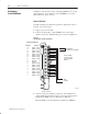
2. Record the input value read by the processor in the BTR file
(word 4 for channel 1). Determine the percentage difference
from 10000 and the sign of the correction.
You can adjust the correction up to +
0.19379%.
A negative correction means that the reading was too high and
you want to subtract a corrective amount from that reading.
A positive correction means that the reading was too low and you
want to add a corrective amount to that reading.
If programming in BCD, the upper limit for the display is A000.
If the overrange bit is set, turn back the voltage reference until the
overrange turns off. Use the difference for the calculation.
For example, if the observed value was 10014, then 10000–10014
= –14, and –14 divided by 10000 = –0.14%.
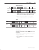
3. Using the following table, select gain correction values that most
nearly add up to the percentage that you determined in step 1.
Select a value only once.
Bit Value
Enter the bit code representing the sum of the corrections into the
lower byte (gain correction) of the calibration word for that
channel.
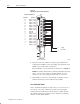
For example, to attain the value of 0.140%, you would add:
Percentage Bit Number
Enter 11011100 in the lower byte of the calibration word for that
channel. This entry would set bits 07 (sign) and 06, 04, 03 and 02
which is –0.1403807, very close to the required –0.14. Remember
to keep the upper byte the same as it was from step 5.