
User Manual


6–6 Module Calibration
2!*(" 1(-, 4 4 3
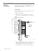
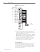
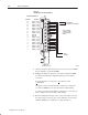
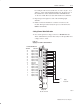
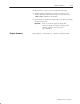
Figure 6.4
Shorting Inputs for Offset Calibration
1
- ,-1
20$
,.21 *$ #
,.21 *$ #
,.21 *$ #
,.21 *$ #
,.21 *$ #
,.21 *$ #
,.21 *$ #
,.21 *$ #
-1 0$#
-1 20$#
,.21 *$ #
,.21 *$ #
,.21 *$ #
,.21 *$ #
,.21 *$ #
,.21 *$ #
,.21 *$ #
,.21 *$ #
$/+(, * #$,1(%(" 1(-,
$/+(, * 2,"1(-,
(/(,& /+
1 -
$.$ 1 %-/ $ "' "' ,,$*
..*3
+
'-/1 $ "' (,.21
-/ ..*3 +
"/-00 $ "' (,.21
"' ,,$*
'-/1(,& *(,)
3. Observe the input value read by the processor (word 4 of the BTR
file for channel 1). It should be 0000.
4. Multiply the difference between your observed value and 0.000
by 3.0933. Determine the magnitude and sign of the required
correction.
You can adjust the correction up to +
127 binary counts
(+
410.56µV).
A negative correction means that the reading was too high and
you want to subtract a corrective amount from that reading.
A positive correction means that the reading was too low and you
want to add a corrective amount to that reading.
5. Enter the magnitude and sign of the correction in binary code into
the upper (offset correction) byte of the calibration word for that
channel. (BTW file, word 20, bits 17–10 for channel 1.)