
User Manual


6–4 Module Calibration
-%$,$(' / / .
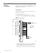
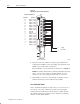
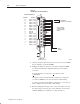
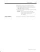
Figure 6.2
Applying 100.00mV for Gain Calibration
1
( '(,
-+!
')-, %!
')-, %!
')-, %!
')-, %!
')-, %!
')-, %!
')-, %!
')-, %!
(, +!
(, -+!
')-, %!
')-, %!
')-, %!
')-, %!
')-, %!
')-, %!
')-, %!
')-, %!
!*&$'% !',$"$,$('
!*&$'% -',$('
$*$'# *&
, (
&
))%.
+
2. After the connections stabilize, request the gain calibration by
setting bit 01 in BTW word 28 and sending a block transfer write
(BTW) to the module. Refer to Table 6.A.
When the BTW is sent, all channels are calibrated to +100.00mV.
NOTE: Normally, all channels are calibrated simultaneously (bits
10–17 of word 28 are octal 0). To disable calibration on any
channel, set the corresponding bit 10 through 17 of word 28.
3. Queue BTRs to monitor for gain calibration complete and any
channels which may not have calibrated successfully.
Save Calibration Values
If any ”uncalibrated channel” bits (bits 10–17 of word 13) are set, a
save cannot occur. Auto–calibration should be performed again,
starting with offset calibration. If the module has a faulty channel,
the remaining functioning channels can be calibrated by inhibiting
calibration on the faulty channel.