
User Manual


6–3Module Calibration
.%$-$(' 1 1 0
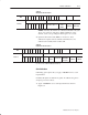
Table 6.A
Write Block Transfer Word 28
Word
Bit
17 16 15 14 13 12 11 10 07 06 05 04 03 02 01 00
'#$$- %$+-$(' !*.!,-! .-(%$+-$('
(+
!- -#!,! $-, -(
!*.!,-!
/!
%.!,
!*.!,-!
$' %
!*.!,-!
"",!- %
NOTE: Normally, all channels are calibrated simultaneously (bits
10–17 of word 28 are octal 0). To disable calibration on any
channel, set the corresponding bit 10 through 17 of word 28.
4. Queue block transfer reads (BTRs) to monitor for offset
calibration complete and any channels which may have not
calibrated successfully. Refer to Table 6.B.
Table 6.B
Read Block Transfer Word 13
Word
Bit
17 16 15 14 13 12 11 10 07 06 05 04 03 02 01 00
'%$+-! #''!%, .-(%$+-$(' --.,
(+
%
.%-
.%-
(- .,!
/! -(
(&)%!-!
$' %
(&)%!-!
"",!- %
(&)%!-!
5. Proceed to Gain Calibration below.
Gain Calibration
Calibrating gain requires that you apply +100.000mV across each
input channel.
Normally all inputs are calibrated together. To calibrate the gain of
an input, proceed as follows:
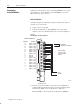
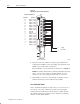
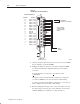
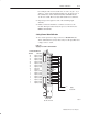
1. Apply +100.000mV across each input channel as shown in
Figure 6.2.