
User Manual


6–2 Module Calibration
2!*(" 1(-, 4 4 3
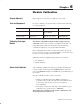
Calibration of the module consists of applying 0.000mV across each
input channel for offset calibration, and +100.000mV across each
input channel for gain correction.
Offset Calibration
Normally all inputs are calibrated together. To calibrate the offset of
an input, proceed as follows:
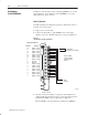
1. Apply power to the module.
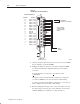
2. Connect shorting links, or apply 0.000mV across each input
channel on the 1771–WI field wiring arm as shown in Figure 6.1.
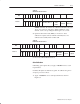
Figure 6.1
Shorting Inputs for Offset Calibration
1
- ,-1
20$
,.21 *$ #
,.21 *$ #
,.21 *$ #
,.21 *$ #
,.21 *$ #
,.21 *$ #
,.21 *$ #
,.21 *$ #
-1 0$#
-1 20$#
,.21 *$ #
,.21 *$ #
,.21 *$ #
,.21 *$ #
,.21 *$ #
,.21 *$ #
,.21 *$ #
,.21 *$ #
$/+(, * #$,1(%(" 1(-,
$/+(, * 2,"1(-,
(/(,& /+
1 -
$.$ 1 %-/ $ "' "' ,,$*
..*3
+
'-/1 $ "' (,.21
-/ ..*3 +
"/-00 $ "' (,.21
"' ,,$*
'-/1(,& *(,)
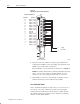
3. After the connections stabilize, request the offset calibration by
setting bit 00 in block transfer write word 28 and sending a block
transfer write (BTW) to the module. Refer to Table 6.A.
When the BTW is sent, all channels are calibrated to 0.000mV.
Performing
AutoĆCalibration