
User Manual

Chapter 6
.%$-$(' 1 1 0
In this chapter we tell you how to calibrate your module.
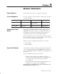
In order to calibrate your input module you will need the following
tools and equipment:
Tool or Equipment Description Model/Type Available from:
+ $,$(' (%-" (.+
& µ + ,(%.-$('
'%("$ - + $,$('
(+ *.$/% '-
'.,-+$% +&$'% '
'- +('' - %
+("+&&$'" - +&$'% !(+
!&$%0 )+( ,,(+,
- ( (+ - (
-
%% '+% 0 (&)'0
$"#%' $"#-,
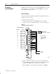
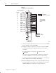
The thermocouple/millivolt input module is shipped already
calibrated. If it becomes necessary to recalibrate the module, you
must calibrate the module in an I/O chassis. The module must
communicate with the processor and industrial terminal.
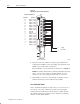
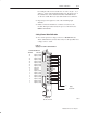
Before calibrating the module, you must enter ladder logic into the
processor memory, so that you can initiate BTWs to the module, and
the processor can read inputs from the module.
Calibration can be accomplished using either of two methods:
• auto–calibration
• manual calibration
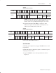
Auto–calibration calibrates the input by generating offset and gain
correction values and storing them in EEPROM. These values are
read out of EEPROM and placed in RAM memory at initialization of
the module.
The auto–calibration routine operates as follows:
• Whenever a block transfer write (BTW) of length 28 is
performed to the module (any time after the module has been
powered up), it interrogates word 28 for a request for
auto–calibration.
• The request can be for the following: offset calibration, gain
calibration, save operation (save to EEPROM).
When using auto–calibration, write transfer calibration words
20 through 27 must contain zeroes.
Chapter Objective
Tools and Equipment
Calibrating Your Input
Module
About AutoĆCalibration