
User Manual


4–4 Module Configuration
! # # "
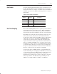
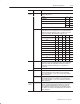
Table 4.C
Bit Settings for the Real Time Sample Mode
Decimal Bits
Octal Bits
15
17
14
16
13
15
12
14
11
13
Sample Time Period
!
Important: Use decimally addressed bit locations for PLC–5
processors.
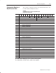
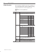
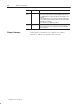
Each channel has an alarm enable bit, an alarm polarity bit, and high
and low alarm values associated with it. These bits and words are
explained in the bit/word definitions in Table 4.E.
You have the ability to calibrate this module using auto–calibration
or by manually setting the individual channel words. Words 20
through 27 in the configuration word (Table 4.E) are the calibration
words for channels 1 through 8 respectively. Calibration is explained
in chapter 6.
Channel Alarms
Calibration