
User Manual


3–6 Module Programming
( '#" + + *
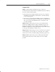
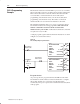
Scan time is defined as the amount of time it takes for the input
module to read the input channels and place new data into the data
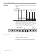
buffer. Scan time for your module is shown in Figure 3.4.
The following description references the sequence numbers in Figure
Figure 3.4.
Following a block transfer write “1” the module inhibits
communication until after it has configured the data and loaded
calibration constants “2”, scanned the inputs “3”, and filled the data
buffer “4”. Write block transfers, therefore, should only be
performed when the module is being configured or calibrated.
Any time after the second scan begins “5”, a block transfer read
(BTR) request “6” can be acknowledged.
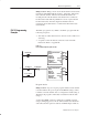
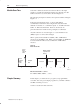
When operated in the default mode (RTS) = 00, a BTR will be
released every 50 milliseconds. When operated in RTS = T, BTR will
be waived until ”T”millseconds, at which time 1 BTR will be
released.
Figure 3.4
Block Transfer Time
#
%"&%
%'
!
" #
#
%"&%
%'
#"(%
!
&' " " " % "
#( )
'# $%#%! #
'%"&%
Internal Scan time = 50msec
T = 100ms, 200ms, 300ms ... 3.1sec.
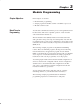
In this chapter, you learned how to program your programmable
controller. You were given sample programs for your PLC–2, PLC–3
and PLC–5 family processors.
You also read about module scan time.
Module Scan Time
Chapter Summary