
User Manual

3–4 Module Programming
2#+)$"1)-, 5 5 "4
Block transfer instructions with the PLC–3 processor use one binary
file in a data table section for module location and other related data.
This is the block transfer control file. The block transfer data file
stores data that you want transferred to the module (when
programming a block transfer write) or from the module (when
programming a block transfer read). The address of the block
transfer data files are stored in the block transfer control file.
The industrial terminal prompts you to create a control file when a
block transfer instruction is being programmed. The same block
transfer control file is used for both the read and write
instructions for your module. A different block transfer control file
is required for every module.
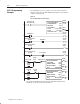
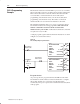
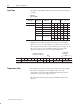
A sample program segment with block transfer instructions is shown
in Figure 3.2, and described below.
Figure 3.2
PLC-3 Family Sample Program Structure
!
!!!
!
!!!!!
!!!!!!!!
!
!!!!!!!!
!
!!!
!
!!!!!
!!!!!!!!
!
!!!!!!!!
20(#211-,
-3&/2.
)1
+-$* /",0'&/
&"% -,& )1
,"#+&
-,&
//-/
,"#+&
-,&
//-/
+-$* /",0'&/
/)1& -,& )1
Program Action
At power–up, the user program examines the BTR done bit in the
block transfer read file, initiates a write block transfer to configure
the module, and then does consecutive read block transfers
continuously. The power–up bit can be examined and used anywhere
in the program.
PLCĆ3 Programming
Example