
User Manual


1–2 Overview of the Thermocouple/Millivolt Input Module
/ '&!.&*) 3 3 2
• all features selectable through programming
• self–diagnostics and status reporting at power–up
• detection of open circuit if thermocouple fails
• automatic offset and gain calibration for each channel
• software calibration of all channels, eliminating potentiometers
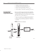
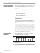
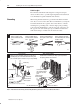
The processor transfers data to and from the module using BTW
(block transfer write) and BTR (block transfer read) instructions in
your ladder diagram program. These instructions let the processor
obtain input values and status from the module, and let you establish
the module’s mode of operation (Figure 1.1).
1. The processor transfers your configuration data and calibration
values to the module using a block transfer write instruction.
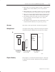
2. External devices generate analog signals that are transmitted to
the module.
Figure 1.1
Communication Between Processor and Module
#(*,2
-#, ,*$,(
* /.+/. #0&!#-
,*!#--*,
%*1)
%#,(*!*/+'#&''&0*'.
)+/. *"/'#
How Analog Modules
Communicate with
Programmable Controllers