
Instruction Manual

Programming and Operation
Chapter 3
3-9
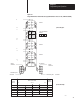
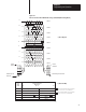
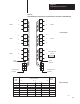
Figure 3.5
Discrete-Contact
Switch Bank Data Storage (SW #4 OFF (Maintained) (Mode)
Same
Same
Same
Same
Same
Terminals
Field Wiring Arm Terminals
Switch
Field Wiring Arm
Terminals
2
2
3
4
5
7
6
5
4
3
2
1
0
6
7
8
9
10371
Data
Table
Word
17
Switch Status Data
Bit Number
10 07
00
XX0
1
2
3
4
5
Diagnostics
Bank 2
Bank 4
1110 0001
Bank 8
-
Bank 1
Bank 3
0110 1010
Bank 7
Bank 9
- -
a) Block Diagram
b) Data Table Map
0110
1010 shows the settings, ON or OFF
, of Switches
S7, S6, S5, S4, S3, S2, S1, S0 of switch bank 5.
11
10 0001 shows the settings, ON or OFF
, of Switches
S7, S6, S5, S4, S3, S2, S1, S0 of switch bank 6.
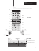
1
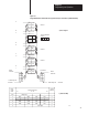
Terminals
Switch
S7 S6 S5 S4 S3 S2 S1 S0
Bank 1
Bank 2
Bank 3
Bank 4
Bank 5
Bank 6
Bank 7
Bank 8
Bank 9
A
B
C
D
E
F
G
H
I
1
2
1
2
0 1101010
1 1100001
S7 S6 S5 S4 S3 S2 S1 S0