
Instruction Manual

Module Preparation, Wiring and
Installation
Chapter 2
2-9
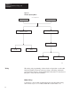
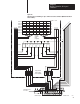
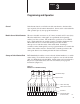
Figure 2.6
Typical
Point-to-point W
iring for up to 72 Discrete Contact Switches (Maintained Switch
Contact Mode)
Bank 9
S7 S6 S5 S4 S3 S2 S1 S0
Enable
I
3 2 1 0
7 6 5 4
B
C
D
E
F
G
H
I
A
A
Discrete
S7 S6 S5 S4 S3
S2 S1 S0Bank 1
Digit Junction
7654
32 10
Field Wiring Arm
Module Inputs
17 I H G F E D C B A
Enable Lines
10367
1
10
Bank 8
Bank 7
Bank 6
Bank 5
Bank 4
Bank 3
Bank 2
Lines
H
G
F
E
D
C
B
Switches
(User
Supplied)
Terminal Strip
(User Supplied)
1771–WF
65432 0
2
3
4
5
6
7
8
9
11
12
13
14
15
16
17
18