Table of Contents Introduction . . . . . . . . . . . . . . . . . . . . . . . . . . . . . . . . . . . . . . 1-1 General . . . . . . . . . . . . . . . . . . . . . . . . . . . . . . . . . . . . . . . . . . . . . . . . . . Typical Applications . . . . . . . . . . . . . . . . . . . . . . . . . . . . . . . . . . . . . . . . . . 1-1 1-2 Module Preparation, Wiring and Installation . . . . . . . . . . . . . . 2-1 General . . . . . . . . . . . . . . . . . . . . . . . . . . . . . . . . . . . . . . . . . . . . .
Table of Contents ii
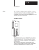
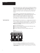
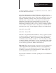
Chapter 1 Introduction General The 1771-IS DC (5V) Multiplexer Input Module, Figure 1.1 reads the status of up to 72 hard contact switch devices through one I/O slot. This information is transferred to the PC processor by block transfer programming. The module can be used with any Allen-Bradley programmable controller that has block transfer capability, an expandable data table, and uses the 1771-I/O structure. Figure 1.
Table of Contents The module reads the status of switch contacts by enabling and reading a “bank” of 8 contacts at a time. This requires that the contacts be grouped and that diode decoupling be used to prevent the appearance of a “phantom” contact closure. Up to 9 banks of 8 contacts per bank can be handled by the module. Power to the switch banks is provided by the module. Contact scanning occurs until the module is interrupted by a read instruction from the PC processor.
Table of Contents WARNING: Outputs of any output module may temporarily change operating state at power-up if placed in the same I/O chassis with a multiplexer module, cat. no. 1771-IS, earlier than hardware revision D, and a power supply (or processor with self-contained power supply) other than 1771-P1 or 1771-P2. To avoid damage to equipment and/or injury to personnel use only multiplexer modules, cat. no. 1771-IS, hardware revision D or later. Important: Hardware revision D is designated by part no.
Table of Contents iv
Chapter 2 Module Preparation, Wiring and Installation General The modes of operation must be set internally to suit the conditions under which the module will be used. In addition, switch contacts and decoupling diodes must be wired to the module.
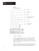
Chapter 2 Module Preparation, Wiring, and Installation Figure 2.1 Mode Selection Dip Switch O N 1 2 3 4 5 6 7 ON 1 ON OFF Always OFF 2 ON OFF 16–Bit Data 12–Bit Data 3 ON OFF Fast Normal 4 ON OFF Momentary (Latched) Contact Mode Maintained Contact Mode 5 ON OFF Always OFF 6 ON OFF Always OFF 7 ON OFF Program Initiated Reset Automatic Reset ON OFF O F F ON OFF OFF 10362 Switch #1 - Always OFF.
Chapter 2 Module Preparation, Wiring and Installation momentary (latched) contact mode or maintained contact mode. (ON for fast scan, OFF for normal scan.) Switch #4 - Maintained Contact Mode/Momentary (latched) Contact Mode. Select the maintained contact mode when storing the status, ON or OFF, of maintained switch contacts. Their status is updated in every scan. Select the momentary (latched) contact mode when storing momentary OFF-ON switch contact transitions.
Chapter 2 Module Preparation, Wiring, and Installation Figure 2.2 Allowable Operating Modes 1771-IS Multiplexer Module Normal Scan Fast Scan Maintained Contacts Momentary (latched) Contacts 16–Bit 12–Bit 16–Bit Program Reset Automatic Reset 10363 Wiring The wiring and programming of the module are dependent on each other. Switch assemblies should be wired according to the wiring schematics presented in this chapter.
Chapter 2 Module Preparation, Wiring and Installation removed or installed in the I/O rack without disconnecting the wiring.) The swingarm can be removed from the I/O rack at the pivot bar. Thumbwheel Switch Wiring Thumbwheel switch terminations are illustrated in Figure 2.3. Digit place labels refer to the position of each digit in a 3-digit or 4-digit thumbwheel switch as follows: MSD and LSD - Most and Least Significant Digit; MD Middle Digit; UMD and LMD - Upper and Lower Middle Digit, respectively.
Chapter 2 Module Preparation, Wiring, and Installation Figure 2.
Chapter 2 Module Preparation, Wiring and Installation Figure 2.
Chapter 2 Module Preparation, Wiring, and Installation Important: The selection of the four field wiring arm terminals, either 2, 3, 4, 5 or 6, 7, 8, 9 is critical for correct transfer of switch status data. The point-to-point wiring schematics show all electrical connections for the first of several parallel switch assemblies. The wiring of additional assemblies is shown conceptually (in the upper portion of each schematic).
Chapter 2 Module Preparation, Wiring and Installation Figure 2.
Chapter 2 Module Preparation, Wiring, and Installation Diode Decoupling Decoupling diodes prevent unwanted currents from circulating through the switch circuits and causing the false appearance of switch closures. Use decoupling diodes when the application calls for more than 8 switch contacts. Some thumbwheel switches have provision at the switch terminals for wiring the diodes. Otherwise, a separate terminal strip should be used for wiring a diode to each switch terminal.
Chapter 2 Module Preparation, Wiring and Installation CAUTION: This module is not compatible with TTL switching. The external power source will damage the module. When selecting BCD thumbwheel switches, be sure that they are equipped with decoupling diodes or that terminals are available on the thumbwheel switch so that the diodes can be wired directly to the switch assembly. The diode polarity must be set for low = TRUE operation.
Chapter 2 Module Preparation, Wiring, and Installation Refer to Figure 2.7. Using needle-nose pliers, place the keying bands between these numbers on the backplane: Between 8 and 10 Between 26 and 28 Figure 2.
Chapter 3 Programming and Operation General Switch status data is stored in the module, transferred to the data table upon request by block transfer instructions, then stored in a data table file until operated upon by user program instructions. Module Scan of Switch Contacts The user-selectable scan rates are 15.3 msec (normal) and 5.1 msec (fast). The nine enable lines, A through I, are sequentially and repeatedly enabled, one line at a time. The enable lines operate in a low = TRUE logic.
Chapter 3 Programming and Operation 4-digit Thumbwheel Switch Data (16-bit storage) Data is loaded into memory based on whether you have selected the maintained or momentary switch contact mode (SWITCH #4). Maintained Contact Mode When 4-digit BCD thumbwheel switches are wired according to the block diagram in Figure 3.2a, the switch settings will be stored automatically in the data table after a block transfer as shown in Figure 3.2b. The first word is reserved for diagnostic data.
Chapter 3 Programming and Operation Figure 3.
Chapter 3 Programming and Operation Momentary Contact Mode When 4-digit BCD thumbwheel switches are wired according to the block diagram in Figure 3.3a, the switch settings will be stored automatically in the data table after a block transfer as shown in Figure 3.3b. The first word is reserved for diagnostic data. Each remaining word stores the 4 digits of the thumbwheel setting.
Chapter 3 Programming and Operation Figure 3.
Chapter 3 Programming and Operation Important: The 16-bit data position (switch #2 ON) should be selected when 4-digit thumbwheel switches or discrete contact switches are used. Otherwise switch status data from these devices can become scrambled when transferred to the data table. Discrete Contact Switch Data (16-Bit storage) Data is loaded into memory on the basis of whether you have selected the maintained or momentary switch contact mode (switch #4).
Chapter 3 Programming and Operation Figure 3.
Chapter 3 Programming and Operation Maintained Control Mode When up to 72 discrete contact switches are wired as switch banks, Figure 3.5a, the settings are stored automatically in the data table after a block transfer as shown in Figure 3.5b. The first word is reserved for diagnostic data. Each remaining word stores the status of two switch banks. The settings of a switch bank are represented by S7, S6, S5, S4, S3, S2, S1, S0.
Chapter 3 Programming and Operation Figure 3.
Chapter 3 Programming and Operation Important: When momentary switch contacts are used, the momentary (latched) contact position (switch #4, ON) should be selected. Otherwise, bits will be reset when the momentary contact switches open and data representing OFF-to-ON transitions can be lost. The maintained contact position (switch #4 OFF) should be selected if the application calls for the use of up to 72 maintained contact switches.
Chapter 3 Programming and Operation Figure 3.
Chapter 3 Programming and Operation Momentary Contact Mode When 3-digit BCD thumbwheel switches are wired according to the block diagram in Figure 3.7a, the switch settings are stored automatically in the data table after a block transfer, as shown in Figure 3.7b. The first word is reserved for diagnostic data. The remaining words store the three digits of the thumbwheel setting. The digits MSD, MD and LSD have been loaded in the order are shown in Figure 3.7.
Chapter 3 Programming and Operation Figure 3.
Chapter 3 Programming and Operation Important: The 12-bit data position (switch #2 OFF) should be selected when 3-digit thumbwheel switches are used. Otherwise switch status data from this device can become scrambled when transferred to the data table. Block Transfer of Switch Data Switch status data can be transferred to the PC processor data table by using block transfer instructions. The Mini-PLC-2/15, PLC-2/30 and PLC-3 programmable controllers use block transfer instructions.
Chapter 3 Programming and Operation Figure 3.8 Example Block Transfer Programming, PLC-2 Family 010 Output Image Table Data Table R 1 Block length code 012 Output Image Table Byte, contains Read Enable Bit and Block Length in binary code.
Chapter 3 Programming and Operation Programming Example, PLC-2 Family Two methods of programming are described: one using block transfer instructions, the other using multiple GET instructions. Refer to Figure 3.8. The data table mapping is the same for both. For this example, 3 words of data are used to transfer the settings of two 4-digit thumbwheel switches. The settings are 9751 and 8642 for thumbwheel switch assembly 1 and 2, respectively. (The first word is reserved for diagnostic data.
Chapter 3 Programming and Operation Programming Considerations, PLC-2 Family The block transfer data address is the address that identifies the block transfer instruction. Care should be taken when assigning these addresses in the data table. Date Address (PLC-2 Family) The data address for a block transfer instruction should be the first available address in the timer/counter accumulated area of the data table. This address is 0308 for the Mini-PLC-2 or -2/15.
Chapter 3 Programming and Operation Figure 3.9 Example Block Transfer Programming, PLC-3 Data Table Maps a) Control File (FB001:0010) Read Bits 17 0010 16 ÉÉ ÉÉ 15 14 RQ EN DN 13 Write Bits 12 11 ÉÉ ÉÉÉÉÉ ÉÉ ÉÉÉÉÉ 07 06 05 04 ER LE SD SE RQ EN DN Rack Number 0011 10 03 02 01 00 ER LE SD SE Bit Control Word (WB001:0010) Mod.
Chapter 3 Programming and Operation length: the number of words to be transferred can be 0-7 depending on the number of switch assemblies. (03) module address: rack, module group and slot number where 1 = HIGH = upper slot, 0 = LOW = lower slot. (121) control file address: location of a 10-word file necessary for block transfer read and write operations, contains the module address in binary, the address of the data file and the block transfer status/control bits.
Chapter 3 Programming and Operation Other Programming Considerations, PLC-2 Family and PLC-3 When programming block transfer instructions the following should also be considered. Automatic/Program Reset, switch #7 When in momentary (latched) contact mode, latched data should be reset after its image is transferred to the data table. It can be reset by program logic (program reset mode) or automatically by the module (automatic reset mode).
Chapter 3 Programming and Operation Figure 3.10 Examples of Program Reset Block Transfer, PLC-2 Family Optional Condition Reset Condition Reset Condition Reset Condition BLOCK XFER READ DATA ADDR: 030 MODULE ADDR: 121 BLOCK LENGTH: 03 FILE 060 – 062 Store Word G 000 012 EN 17 112 DN 17 012 PUT 012 16 Multiple GET, PLC–2 Family Optional Condition Reset Condition Use bit 6 if module is in the left slot of module group.
Chapter 3 Programming and Operation In automatic reset mode, the module resets its data and stores new latched data after each block transfer. Allow at least 20ms between block transfers for the module to store new data. A method for doing this is shown in Figure 3.11. Figure 3.
Chapter 3 Programming and Operation PLC–3 Block Transfer B001:0010 B002:0000 BLOCK XFER DONE U 00 15 T0001 15 B002:0000 L 00 TIMER DONE B002:0000 BTR BLOCK XFER READ 001 RACK : 2 GROUP : MODULE: 1 = HIGH DATA: FD002:0012 LENGTH: 3 CNTL: FB001:0010 00 TON TIMER ON T0001 0.01 SECOND TP = 2 TA = 0 T0001 / CNTL EN 12 CNTL DN 15 CNTL ER 13 T0001 TE 17 T0001 TD 15 NOTES: a) Module located in rack 1, module group 2, slot 1. b) Timer allows at least 20ms between block transfers.
Chapter 3 Programming and Operation This can be done by examining the block transfer done bit for an ON condition. An EXAMINE ON instruction addressed to the done bit should be a logic condition for any further manipulation of transferred data. The done bit for the PLC-2 family and PLC-3 programming example is 112/17 and WB001:0010/15, respectively. WARNING: Program the examination of the block transfer done bit as a condition for subsequent data manipulation following each block transfer.
Appendix A Specifications Module Inputs Up to four 4–digit BCD Thumbwheel Switches or Module Current Requirement 800 mA max @ 5V DC from the backplane Up to six 3–digit BCD Thumbwheel Switches or Maximum Switch Cable Distance 400 feet Up to 72 Discrete Contact Switches (Maintained or Momentary contact) Ambient Temperature Rating 0–60 0C Operational –20 to +850 C Storage Diode Decoupling is required for more than 8 Switch Contacts Module Location Any Bulletin 1771 I/O Rack location except the left–m
Table of Contents ii
Index Symbols **Empty**, 2-11 , 3-19 Numbers 4–digit thumbwheel switch data, 3-2 A automatic, 3-22 D Data buffering, 3-23 data storage, 3-6 Decoupling, 2-10 Diagnostics, 3-23 Dip switch settings, 2-1 Discrete contact switch data, 3-6 Discrete switch bank wiring, 2-8 E external power, 2-10 K Keying, 2-11 L Low = TRUE, 2-10 I–1 I
I–2 Index S M Mode selection dip switch, 2-1 Module scan of switch contacts, 3-1 Module wiring, 2-4 O od switch data, 3-14 P PLC–2 family, 3-14 R reset, 3-20 I–2 selection, 2-11 Specifications, A-1 T Thumbwheel switch wiring, 2-5 Typical Applications, 1-2 W When to use 16–bit or 12–bit storage, 2-2 Wiring, 2-4 with 3–digit thumbwheel switch data, 3-10