
Installation Instructions

RTD Input Module8
Publication 1771Ć5.63 - November 1998
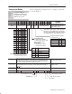
Use the following table to read data from your input module.
Dec. Bits 15 14 13 12 11 10 09 08 07 06 05 04 03 02 01 00
Description
Octal Bits 17 16 15 14 13 12 11 10 07 06 05 04 03 02 01 00
Description
Word 1 RTS Channel overrange EE PU Channel underrange
EEPROM status bit - (EE) This bit is set if EEPROM
values could not be read.
Real time sample fault bit - (RTS) Real
time sample timeĆout bit.
Power up bit - (PU) Set when the module is alive
but not yet configured.
Underrange bits for each channel; set when
input is below the normal operating range for
copper or platinum RTD. Bit 00 for input 1, bit 01
for input 2, etc.
Overrange bits for each channel. set when the input is
above the normal operating range. Bit 10 for input 1, bit
11 for input 2, etc.
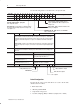
2 Not used Channel Polarity Not Used Channel overflow Channel overflow, channel polarity
Channel overflow - When set, indicate that default bias has been subtracted from the input value.
Only the remainder is shown in the data word. Bit 00 for input 1, bit 01 for input 2, etc. Default bias is
automatically applied when BCD formatted data cannot be displayed. This will occur when measuring
temperatures in Fahrenheit larger than 999.9 degrees. The default bias value which is subtracted is
1000.0.
Channel Polarity - Sign bits for each channel. When set indicate that a certain input is negative. Bit 10
corresponds to input 1, bit 11 to input 2, etc. These bits are used for BCD and signed magnitude data
formats.
3, 4, 5, 6, 7, 8 Channel 1Ć6 Data - Input data words for each channel. Word 3 to channel 1, word 4 to channel 2, etc.
The data words must be multiplied or divided by a factor if whole numbers need to be displayed. See
table below.
Channel 1Ć6 Data
If Then
you are reading temperature in
o
For
o
C there is an implied decimal point (XXX.X) after the
least significant digit. Resolution is 0.1
o
.
you are reading resistance in milliohms (copper
RTDs) (BTW word 1, bit 10 = 1)
there is an implied decimal point (XXX.XX).
you are reading resistance in milliohms (all
other RTDs) (BTW word 1, bit 10 = 0)
multiply the data word by 30 to get the actual value
in milliohms. Resolution is 30 milliohms.
9 Not used Channel failed calibration FC EE Not used S G O AutoĆcalibration status
Offset calibration complete
Gain calibration complete
Save complete
EEPROM fault
Faulty calibration (no save)
Default Configuration
If a write block of five words with all zeroes is sent to the module,
default selections will be:
• BCD data format
• 100 ohm platinum RTD
• temperature in degrees C
• real time sampling (RTS) = inhibited (sample time = 50ms)