
Installation Instructions

RTD Input Module6
4!+(" 3(.- 9 .5$,!$1
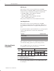
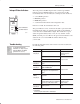
Use the following diagrams to ground your
I/O chassis and input module. Follow these
steps to prepare the cable:
Refer to Wiring and Grounding Guidelines,
publication 1770-4.1 for additional
information.
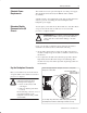
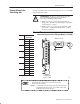
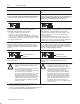
$,.5$ +$-&3' .% " !+$
) "*$3 %1., 3'$ " !+$
4++ 3'$ %.(+ 2'($+# -# ! 1$
#1 (- 6(1$ %1., 3'$ (-24+ 3$# 6(1$2
1$ #1 (-
6(1$
-24+ 3$#
6(1$2
.(+
2'($+#
6(23 3'$ %.(+ 2'($+# -# #1 (-
6(1$ 3.&$3'$1 3. %.1, 2(-&+$ 231 -#
33 "' &1.4-# +4&
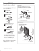
'$- 42(-& 2'($+#$# " !+$ 6(1$ &1.4-# 3'$ %.(+
2'($+# -# #1 (- 6(1$ .-+8 3 .-$ $-# .% 3'$ " !+$
$ 1$".,,$-# 3' 3 8.4 61 / 3'$ %.(+ 2'($+# -#
#1 (- 6(1$ 3.&$3'$1 -# ".--$"3 3'$, 3. "' 22(2
,.4-3(-& !.+3
3 3'$ .//.2(3$ $-# .% 3'$ " !+$ 3 /$ $7/.2$#
2'($+# -# #1 (- 6(1$ 6(3' $+$"31(" + 3 /$ 3. (-24+ 3$
(3 %1., $+$"31(" + ".-3 "3
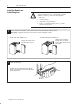
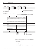
73$1- +93..3'
2'$12
'1$ #9%.1,(-& 2"1$6
'($+# -# 1 (-
36(23$# 3.&$3'$1
73$-# 2'($+# 3. 3$1,(- 3(.- /.(-3
7/.2$ )423 $-.4&' " !+$ 3. #$04 3$+8
3$1,(- 3$ (--$1 ".-#4"3.12
2$ '$ 3 2'1(-* 34!(-&
.1 .3'$1 24(3 !+$
(-24+ 3(.- 6'$1$ 6(1$
$7(32 " !+$ ) "*$3
1.4-#(-& 34#
2$ 3'$ "4/ 6 2'$1 (% "1(,/9.- +4&2 1$ -.3 42$#
'$- 8.4 ".--$"3 &1.4-#(-& ".-#4"3.12 3. 3'$ "' 22(2
&1.4-#(-& 234# /+ "$ 23 1 6 2'$1 4-#$1 3'$ %(123 +4& 3'$-
/+ "$ -43 6(3' " /3(5$ +."* 6 2'$1 .- 3./ .% $ "' &1.4-# +4&
1.4-# 4&
1.4-# 4&
3 1
2'$1
' 22(2
(#$ + 3$
43 -# /3(5$
2'$1
'($+# -# 1 (-
36(23$# 3.&$3'$1
43