Installation Instructions Digital ac/dc (24V) Input Module Catalog Number 1771-IND, Series C Topic Page Important User Information 2 Before You Begin 3 Power Requirements 3 Prevent Electrostatic Discharge 4 Set the Delay-time Jumper 5 Key the Backplane 6 Install the Module 7 Connect Wiring 8 Troubleshoot with the Status Indicators 10 Specifications 10 Publication 1771-IN052B-EN-P - April 2006
Digital ac/dc (24V) Input Module Important User Information Solid state equipment has operational characteristics differing from those of electromechanical equipment. Safety Guidelines for the Application, Installation and Maintenance of Solid State Controls (publication SGI-1.1 available from your local Rockwell Automation sales office or online at http://literature.rockwellautomation.com) describes some important differences between solid state equipment and hard-wired electromechanical devices.
Digital ac/dc (24V) Input Module 3 Environment and Enclosure ATTENTION This equipment is intended for use in a Pollution Degree 2 industrial environment, in overvoltage Category II applications (as defined in IEC publication 60664-1), at altitudes up to 2000 meters without derating. This equipment is considered Group 1, Class A industrial equipment according to IEC/CISPR Publication 11.
Digital ac/dc (24V) Input Module Prevent Electrostatic Discharge The ac/dc input module is shipped in a static-shielded bag to guard against electrostatic discharge damage. Observe the following precautions when handling the module. ATTENTION This equipment is sensitive to electrostatic discharge, which can cause internal damage and affect normal operation. Follow these guidelines when you handle this equipment: • • • • • • Touch a grounded object to discharge potential static.
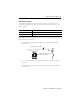
Digital ac/dc (24V) Input Module 5 Set the Delay-time Jumper Your module is equipped with an adjustable delay-time jumper. Use the jumper to select between two input-channel delay times. The delay time you choose applies to all 16 of the module’s channels. Use This Delay Time If You Want To 5 ms Detect typical input readings 20 ms Prevent detection of false inputs in high-noise environments The module is shipped with the delay-time jumper preset to 5 ms.
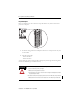
Digital ac/dc (24V) Input Module Key the Backplane Place your module in any slot in the chassis except the leftmost slot, which is reserved for processors or adapters. 1. Position the keying bands in the backplane connectors to correspond to the key slots on the module. 2. Place the keying bands: - between 10 and 12 - between 14 and 16 You can change the position of these bands if subsequent system design and rewiring makes insertion of a different type of module necessary.
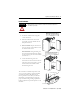
Digital ac/dc (24V) Input Module 7 Install the Module ATTENTION Make certain that you do not install this module into a chassis slot keyed for a 1771-IAD/D input module. Install the module and secure it in the chassis. 1. Position the module in the card guides for the chosen slot 1771-A1B, 1771-A2B, 1771-A3B, 1771-A3B1, 1771-A4B I/O Chassis Locking Tab 2. Slide the module into the chassis and press firmly to seat the module into the backplane connector. Card Guides 3.
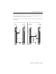
Digital ac/dc (24V) Input Module Connect Wiring Connect your I/O devices to the field wiring arm, cat. no. 1771-WH, shipped with the module. ATTENTION Remove power from the 1771 I/O chassis backplane before you install this module. Failure to remove power from the backplane could cause: • module damage or degradation of performance. • injury or equipment damage due to possible unexpected operation. You can use an ac (24V) output module (cat. no.
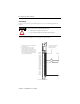
Digital ac/dc (24V) Input Module 9 You can also use an output module (cat. no. 1771-ON) to directly drive terminals on an ac/dc (24V) input module (cat. no. 1771-IND/C), but you must use a 470 Ω, 3 W resistor between the output terminal and L2 (common) as shown below. Use the same ac power source to power both modules to ensure proper phasing and prevent module damage. Driving a 1771-IND/C Module with a 1771-OND Module ac/dc (24V) Input Module (cat. no. 1771-IND/C) ac (24V) Output Module ( (cat. no.
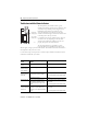
Digital ac/dc (24V) Input Module Troubleshoot with the Status Indicators Module-active Indicator (green) ACTIVE 00 10 01 11 02 12 03 13 04 14 05 15 06 16 07 17 00 to 17 Status Indicators (red) 10429-I The front panel of your module contains 1 green module-active indicator, and 16 red status indicators. The 1771-IND/C input module performs diagnostics in a handshaking mode when first powered up. Upon successful completion of the diagnostics, the green module-active indicator lights.
Digital ac/dc (24V) Input Module 11 Specifications ac/dc (24V) Input Module Catalog Number 1771-IND/C Attribute Value Module Location 1771-A1B, 1771-A2B, 1771-A3B, 1771-A3B1, 1771-A4B or later I/O chassis 1771-AM1, 1771-AM2 I/O chassis Input Voltage, Nom Input voltage: 24V ac, 50…60 Hz; 24V dc Input Current, Nom 9.1 mA @ 24V ac, 60 Hz; 8.1 mA @ 24V ac, 50 Hz; 3.2 mA @ 24V dc On-state Voltage Range 16…30V ac; 12…30V dc On-state Current, Min 6 mA @ 60 Hz; 1.
Environmental Specifications Attribute Value Operating Temperature IEC 60068-2-1 (Test Ad, Operating Cold), IEC 60068-2-2 (Test Bd, Operating Dry Heat) IEC 60068-2-14 (Test Nb, Operating Thermal Shock) 0…60 °C (32…140 °F) Nonoperating Temperature IEC 60068-2-1 (Test Ab, Unpackaged Nonoperating Cold), IEC 60068-2-2 (Test Bb, UnpackagedNonoperating Dry Heat) IEC 60068-2-14 (Test Na, Unpackaged Nonoperating Thermal Shock) -40…85 °C (-40…185 °F) Relative Humidity IEC 60068-2-30 (TestDb, Unpackaged Damp H