
User Manual
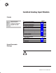

Isolated Analog Input Module6
/'& .&*) 3 *0"(",
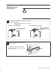
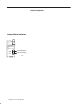
Connect your I/O devices to the field wiring arm (cat. no. 1771-WF)
shipped with the module.
!
ATTENTION: Remove power from the 1771 I/O
chassis backplane and field wiring arm before
removing or installing an I/O module.
• Failure to remove power from the backplane or
wiring arm could cause module damage, degradation
of performance, or injury.
• Failure to remove power from the backplane could
cause injury or equipment damage due to possible
unexpected operation.
)'*$ */, "
)'*$ */, "
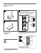
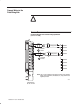
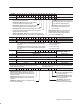
Connection Diagram for the Isolated Analog Input Module
(cat. no. 1771ĆIL/D)
%))"'
%))"'
%))"'
%))"'
%))"'
%))"'
%))"'
%))"'
&"'! &,&)$ ,(
. * 3
3
NOTE: %" 3 (*!/'" !*"- )*. -/++'2 '**+ +*1", #*, '**+ +*1","!
)'*$ -*/, "- .,)-(&..",- .,)-!/ ",- ". **+ +*1", (/-. "
-/++'&"! 2 .%" /-",
+
+
–
–
/) .&*)'
,*/)!
/) .&*)'
,*/)!
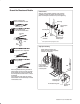
Connect Wiring to the
Field Wiring Arm