
Manual

Troubleshooting
Chapter 7
7-4
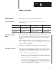
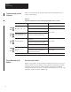
Status Reported in Words 13 and 14
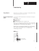
Design your program to monitor over/under alarm bits, and to take appropriate
action depending on your application requirements. You may also want to
monitor these bits while troubleshooting with your industrial terminal.
Bits 00-07 each represent an input for channels 1-8, respectively. For example,
bit 04 represents input channel 5. The module sets a bit (1) to indicate it has
detected an alarm condition. Refer to Table 7.D.
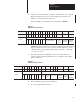
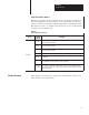
T
able 7.D
Status
Reported in W
ords 13 and 14
Word
Decimal
Bit
(Octal Bit)
Description
Word 13
Bits 00-07
(00-07)
Low Alarm bits for channels 1 through 8 respectively. Each bit
represents an alarm indicator for that channel. When the bit is set, the
value of that channel is below the low alarm value.
Word 14
Bits 00-07
(00-07)
High Alarm bits for channels 1 through 8 respectively. Each bit
represents an alarm indicator for that channel. When the bit is set, the
value of that channel is above the high alarm value.