
Manual

Chapter
5
5-1
Module Status and Input Data
In this chapter you will read about:
reading data from your module
block transfer read data format
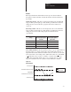
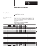
Block transfer read programming moves status and data from the input
module to the processor’s data table in one I/O scan (Figure 5.1). The
processor’s user program initiates the request to transfer data from the
input module to the processor.
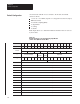
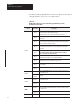
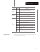
Figure 5.1
Word
Assignments for the Isolated Analog Input Module
(1771-IL series B) Block Transfer Read
Decimal Bits 15 14 13 12 11 10 09 08 07 06 05 04 03 02 01 00
Octal Bits 17 16 15 14 13 12 11 10 07 06 05 04 03 02 01 00
Word 1 Not used A HF IA IF RTS IS OR PU Status word
2 Not used 8 7 6 5 4 3 2 1 Underrange bits - Channels 1-8
3 Not used 8 7 6 5 4 3 2 1 Overrange bits - Channels 1-8
4 Not used 8 7 6 5 4 3 2 1 Polarity bits - Channels 1-8
5 Channel 1 Input Channel 1 Input
6 Channel 2 Input Channel 2 Input
7 Channel 3 Input Channel 3 Input
8 Channel 4 Input Channel 4 Input
9 Channel 5 Input Channel 5 Input
10 Channel 6 Input Channel 6 Input
11 Channel 7 Input Channel 7 Input
12 Channel 8 Input Channel 8 Input
13 Not used 8 7 6 5 4 3 2 1 Low Alarm Bits
14 Not used 8 7 6 5 4 3 2 1 High Alarm Bits
15 8 7 6 5 4 3 2 1 CF EF Not used S G O Calibration Status Bits
Chapter
Objectives
Reading Data From Your
Module