
Manual

Module Configuration
Chapter 4
4-3
T
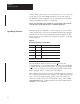
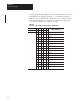
able 4.B
Input
V
oltage and Current Ranges for the Analog Input Module
Nominal Voltage
or Current Range
Default Scaling
BCD Output Range
Voltage or
Current Per Bit
Data from
A/D Converter
Voltage or
Current Per Bit
+1 to +5V 0000 to +4095 0.98mV 3063 to 15316 0.33mV
0 to 5V 0000 to +4095 1.22 mV 32768 to 15316 0.33mV
-5 to +5V -4095 to +4095 1.22mV -15316 to 15316 0.33mV
-10 to +10V -4095 to +4095 2.44mV -30632 to 30632 0.33mV
0 to +20mA 0000 to +4095 0.0049mA 0 to 15316 0.0013mA
+4 to +20mA 0000 to +4095 0.0039mA 3063 to 15316 0.0013mA
-20 to +20mA -4095 to +4095 0.0049mA -15316 to 15316 0.0013mA
Note:
V
oltage and current input ranges are selectable on a per channel basis.
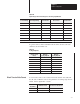
To get the same resolution available from the A/D converter, scale each
channel as shown in Table 4.C.
T
able 4.C
Scaling
Endpoints
Voltage/Current
Range
Minimum
Scaling Endpoint
Maximum
Scaling Endpoint
+1 to 5V 3063 15316
4 to 20mA 3063 15316
0 to 5V 0 15316
0 to 20mA 0 15316
-5 to 5V -15316 15316
-20 to 20mA -15316 15316
-10 to 10V -30632 30632
0 to 10V -30632 30632
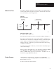
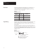
You select the format to enter values in the block transfer write table. Bit
08 (10 octal) of BTW word 2 sets the parameters for scaling, high and low
alarms, and the digital filter constant.
Decimal Bit 08
Octal Bit 10
BTW Data Format You must enter all values in:
0 BCD (default) BCD
1 Two’s Complement Binary Two’s Complement Binary
Block T
ransfer W
rite Format