
Manual

Communicating With
Y
our Module
Chapter 3
3-5
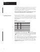
Scan time is defined as the amount of time it takes for the input module to
read the input channels and place new data into the data buffer. Scan time
for your module is shown in Appendix A.
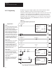
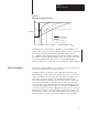
Figure 3.4
Block
T
ransfer T
ime
Block
Transfer
Write
Time
End of Block
Transfer Write
Configure
Time
1st
Scan
2nd Scan
3rd Scan
Module available
to perform block transfer
1 2 3 456
10529-I
Internal Scan time = 50ms
T = 100ms, 200ms, 300ms, 3.1s.
The following description references the sequence numbers in Figure 3.4.
Following a block transfer write (1) the module inhibits communication
until after it has loaded the new configuration data (2), scanned the inputs
and/or outputs (3), and filled the data buffer (4). Configuration block
transfers, therefore, should only be performed when the module is being
configured or calibrated.
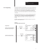
Any time after the buffer is filled (4), a block transfer read (BTR) request
can be acknowledged.
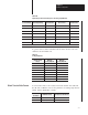
When operated in the default mode, new data will be available for a BTR
every 50 milliseconds. When operated in real time sample mode
(RTS = T), BTRs will be ignored by the module for “T” milliseconds, at
which time a single BTR will be allowed.
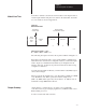
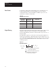
In this chapter, you learned how to program your programmable
controller. You were given sample programs for your PLC-2, PLC-3 and
PLC-5 family processors.
You also read about module scan time.
Module
Scan T
ime
Chapter Summary